vinyl cat sticker and geneva drive kinetic sculpture
vinyl cutting
Toward the end of the prior class period I was trained on how to use the Roland GS-24 vinyl cutter by teaching staff member and resident expert, Victoria Shen.
I wanted to convert a drawing I had to something that could be made into a vinyl sticker so I used Inkscape to convert a drawing of my cat my wife had commissioned from illustrator and RISD alumna Sarah Lee. I first used the "Trace Bitmap" function to get a rough conversion of the drawing to vectorized layers by brightness. Next I manually traced the outline of the shape with lines, added filled regions, and set the fill and line stroke to black with a line thickness of 0.8mm. I then exported my traced design to a png image, re-imported it into Inkscape, and traced the design again. I did this to cleanly merge all of the traced elements together into a single object (Inkscape's union command seemed to fail). I then transferred the resulting svg vector file to the plotter cutter and cut the design.
Unfortunately 0.8mm was too thin of a line stroke to work well. The plotter cutter was able to cut lines with adequate precision, but I could not successfully transfer and peel the surrounding negative space in the drawing without also pulling up the thin lines. I went back to the original traced drawing, raised the line with to 2mm, and repeated the export and trace procedure. An svg with the thicker lines worked well!
With thicker lines, the sticker was able to be applied: transfer film was applied, the backing was peeled, negative space was removed, and it was adhered to my personal laptop.
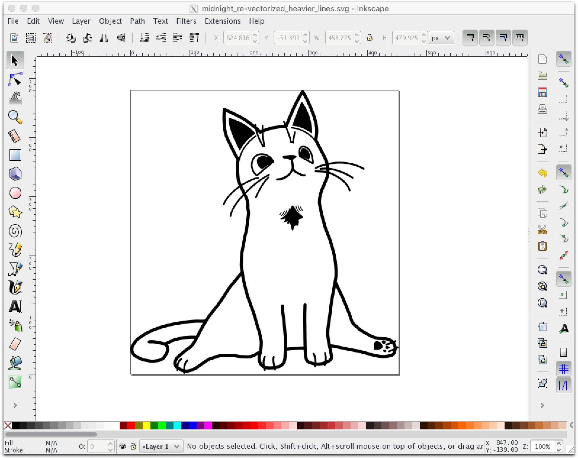

(one whisker was relocated in the process)
kinetic sculpture
For this the assignment due 2020-02-18 we were tasked with making a kinetic sculpture.
To gather ideas I perused a collection of historic illustrations of 507 mechanical mechanisms created by Henry T. Brown in 1868. It was originally published as a book but is now also available on a website where a subset of the mechanisms have been animated. I found these to be appealing:
- http://507movements.com/mm_101.html
- http://507movements.com/mm_125.html
- http://507movements.com/mm_212.html
- http://507movements.com/mm_215.html
- http://507movements.com/mm_223.html
I also took a look around the web for other sources of inspiration and came across this website of kinetic sculptures, with many geared.
I decided to prototype a mechanism for interval partitioning of mosquitoes collected in the field, to direct caught specimens to one of several sample bottles that are swapped out at defined times of the day. A similar partitioning mechanism has been described previously, and was powered by a wound spring or a weight and pulley driving an escapement wheel. In that design, an electrically-actuated solenoid (triggered by an actual analog clock sweeping the hour hand over a contact) was used to release the escapement pallets and allow advancement to the next bottle position. This approach is limited by the potential energy that can be stored in a given spring or pulley weight and the space available.
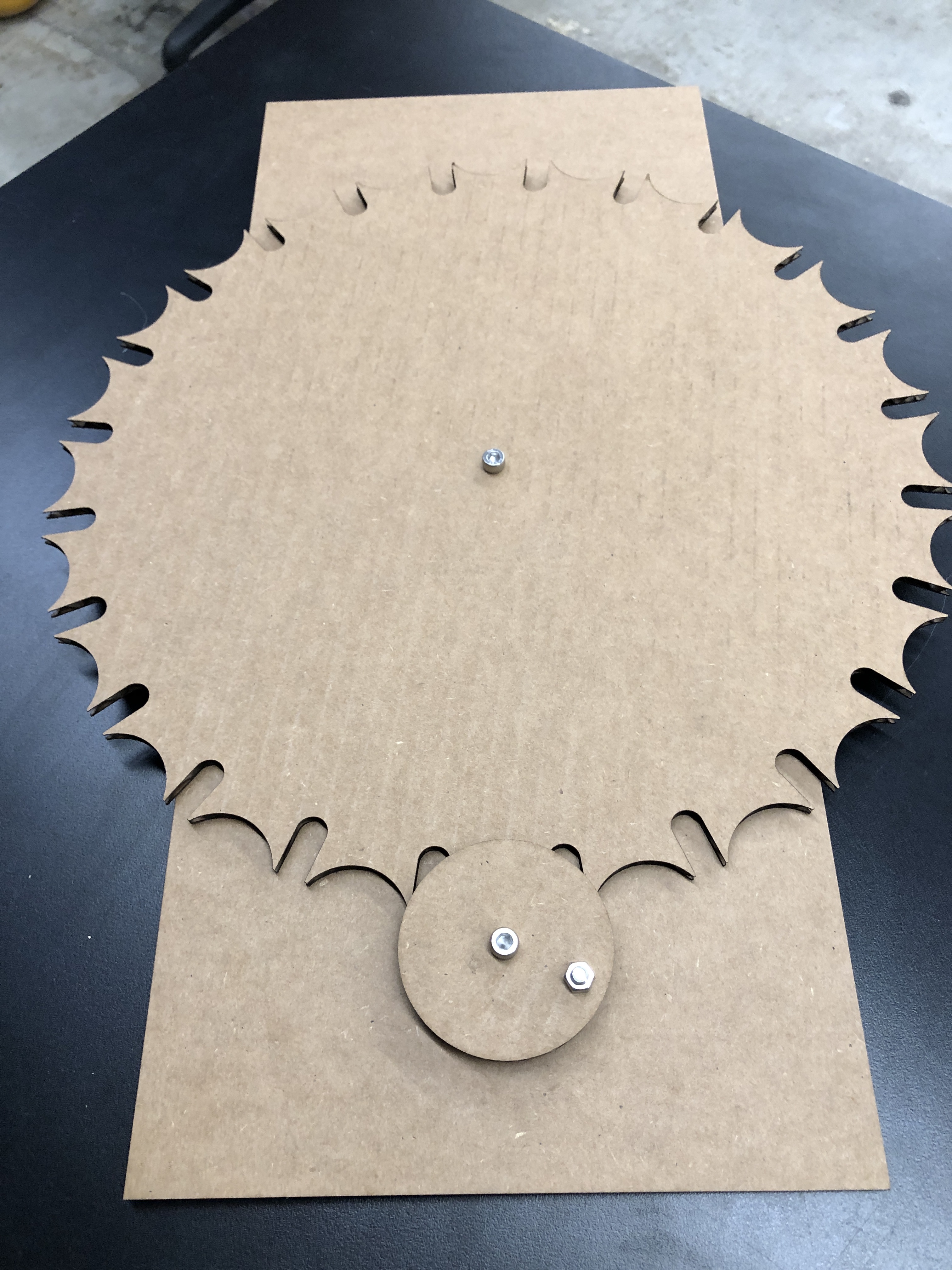
I wanted to try using a small DC motor and a "Geneva drive" gear mechanism to change the sample bottle positions. A Geneva drive converts continuous rotary motion into intermittent rotary motion with mechanically indexed/locked positions. I found this Geneva drive simulator and used it to get a sense of the geometry required. I created a parametric model of a Geneva drive mechanism in Fusion 360.
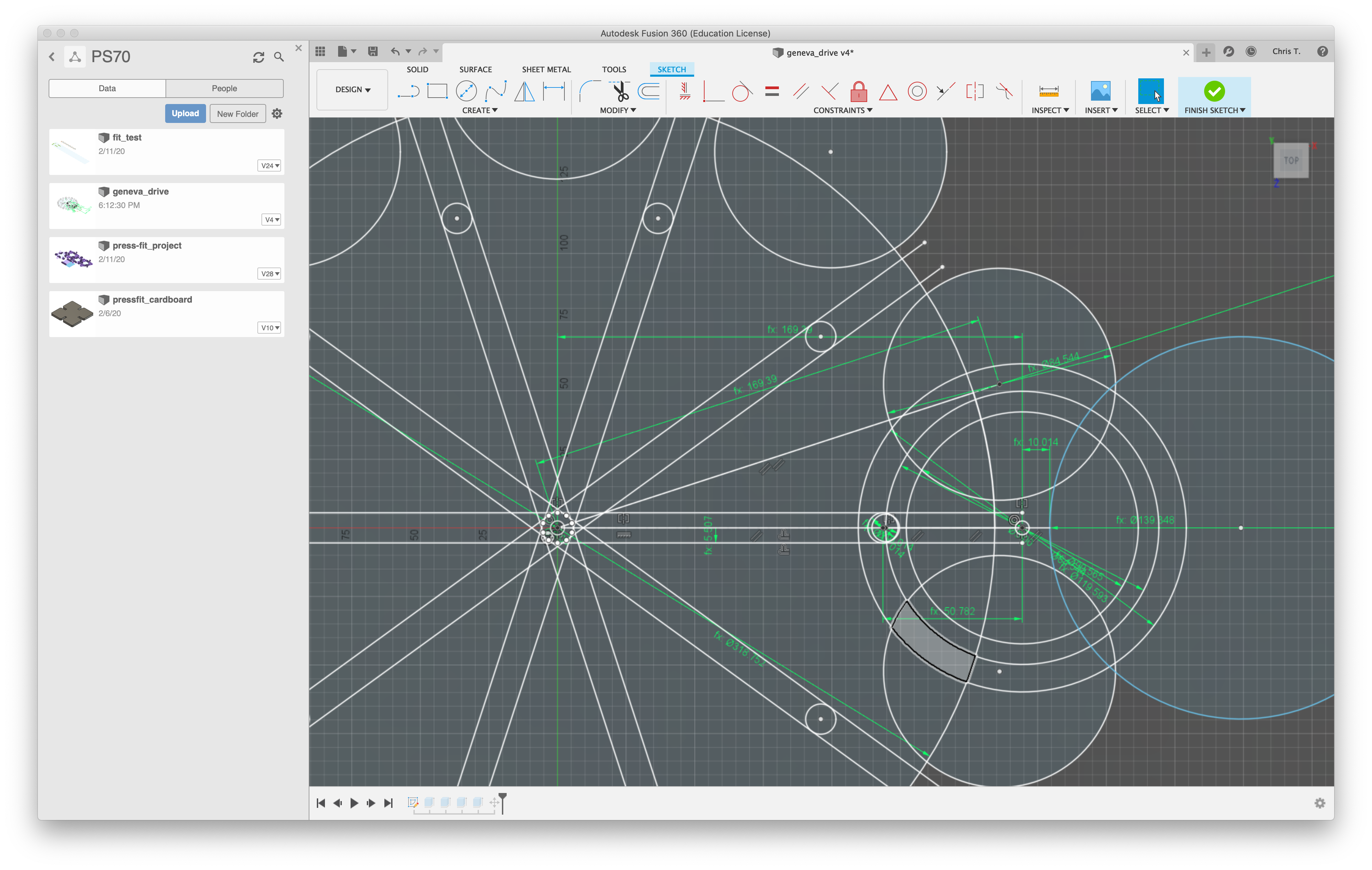

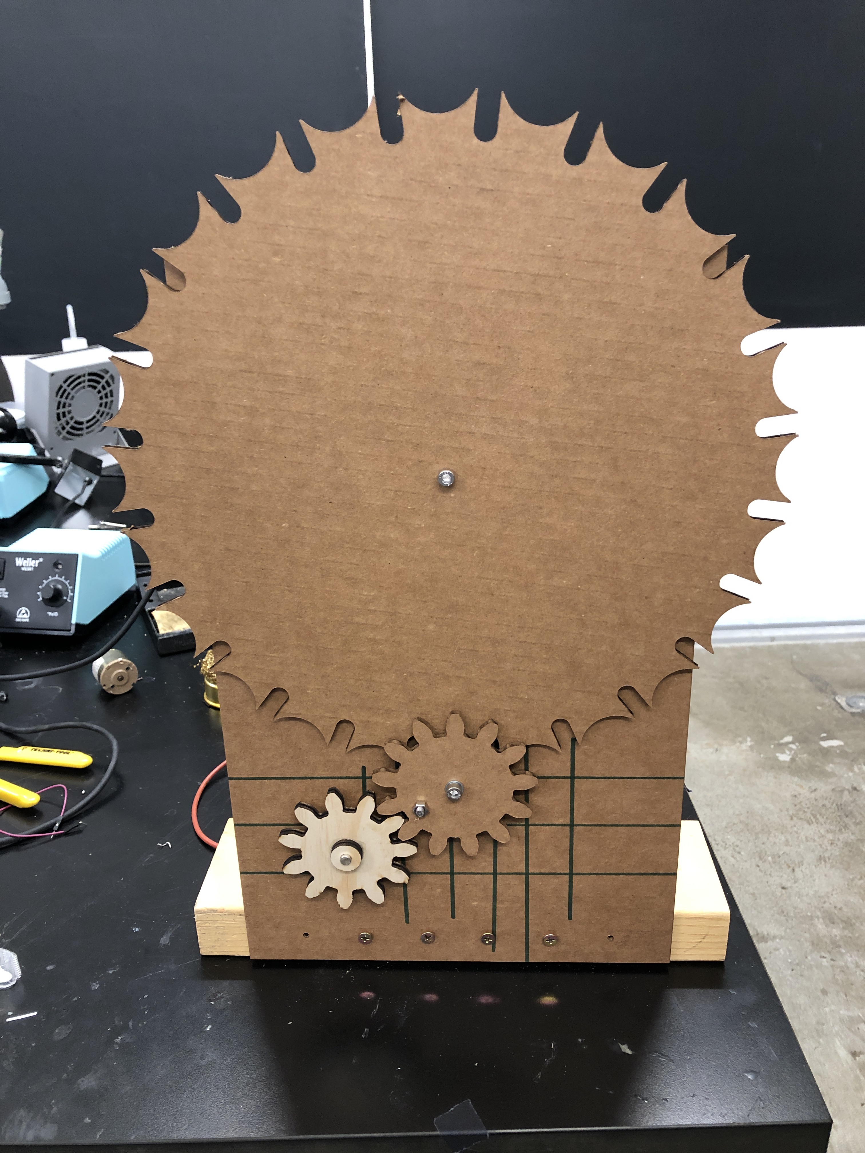
The parameters are not perfectly dialed in for all scales (especially relation to the sample bottle diameter), but they work well enough. I was able to generate a ten-position Geneva gear, and then one with 24 positions.
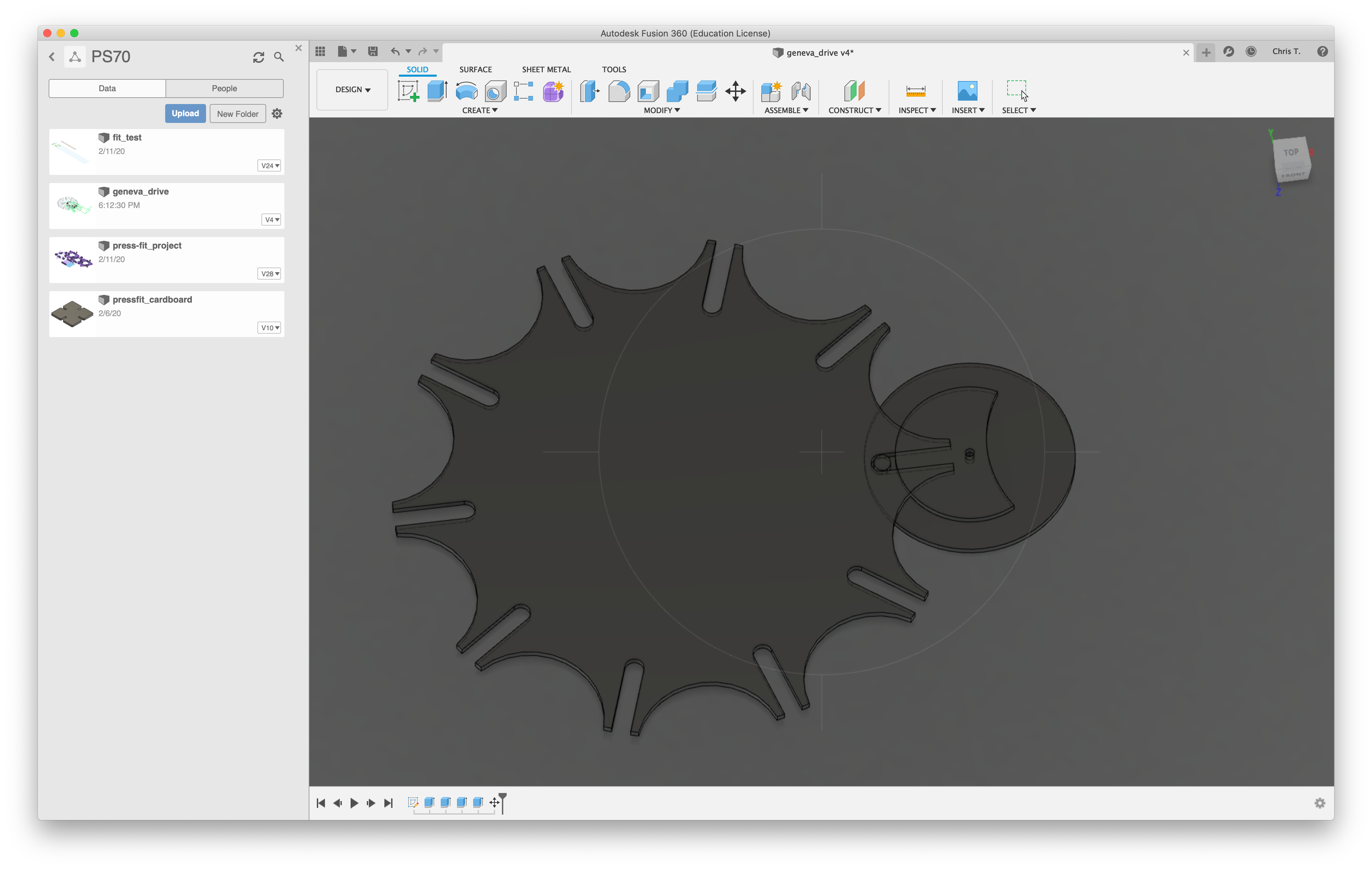
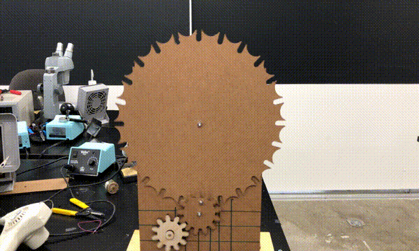
I laser cut the parts out of cardboard to test, with an M5 machine screw as the drive pin. The mechanism worked! Unfortunately I did not have attachment points to drive the system!
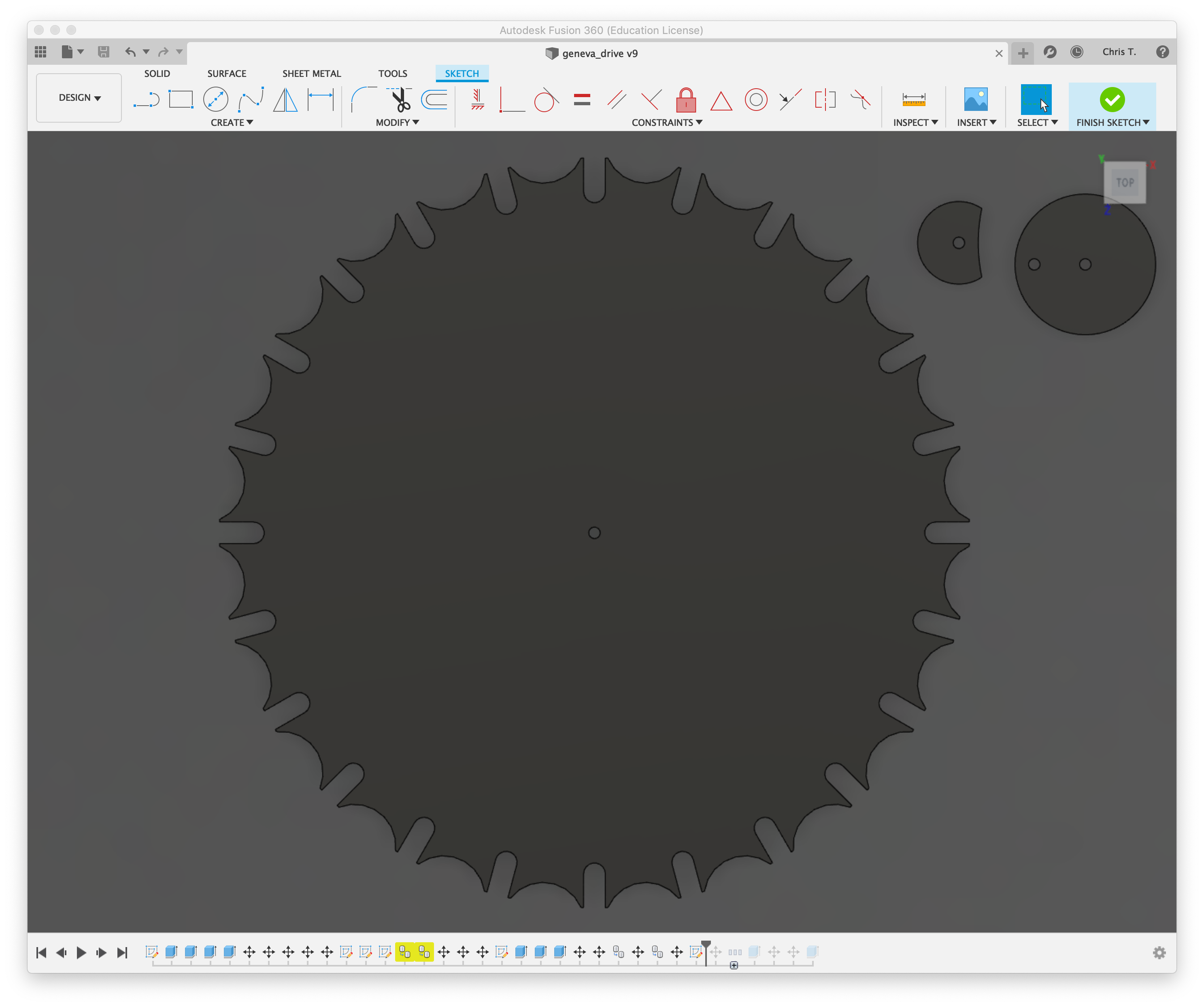
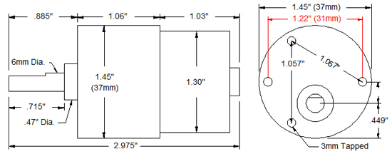
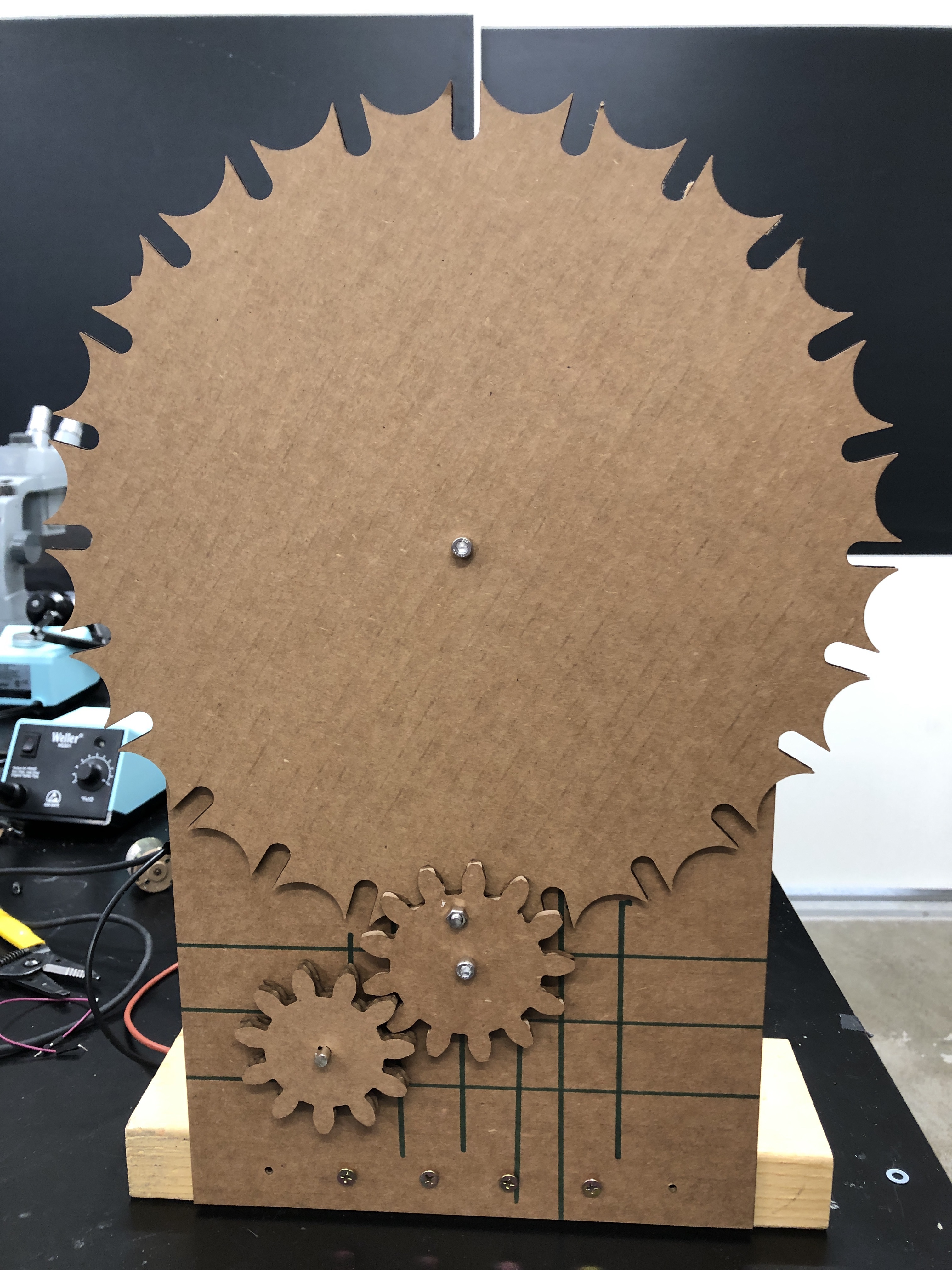
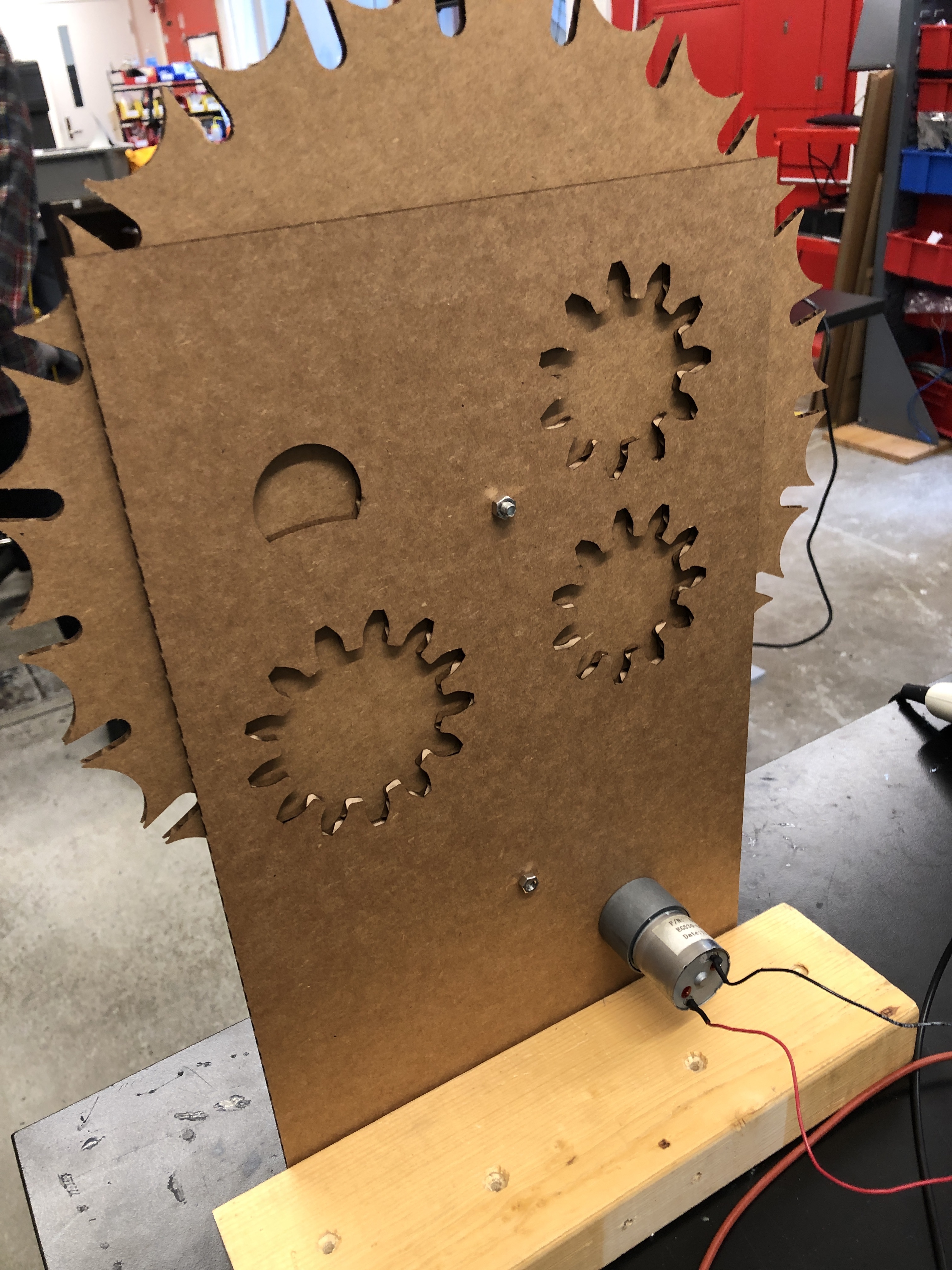
I added mounting holes for a motor to the base plate and involute spur gears to power the Geneva drive. I found a mechanical drawing for the "60218" gearmotor online, and added the screw hole pattern to the base plate.
I generated the gears using the "Spur gear" script/add-on in Fusion 360. In order to modify the gear design I had to project the 3D body to a sketch and then project that sketch into a sketch I had made with the motor shaft cross-section. I gave each gear a prime number of teeth so that the greatest common denominator of the tooth count between them is 1. That way any wear between the gears will be distributed over all of the teeth.

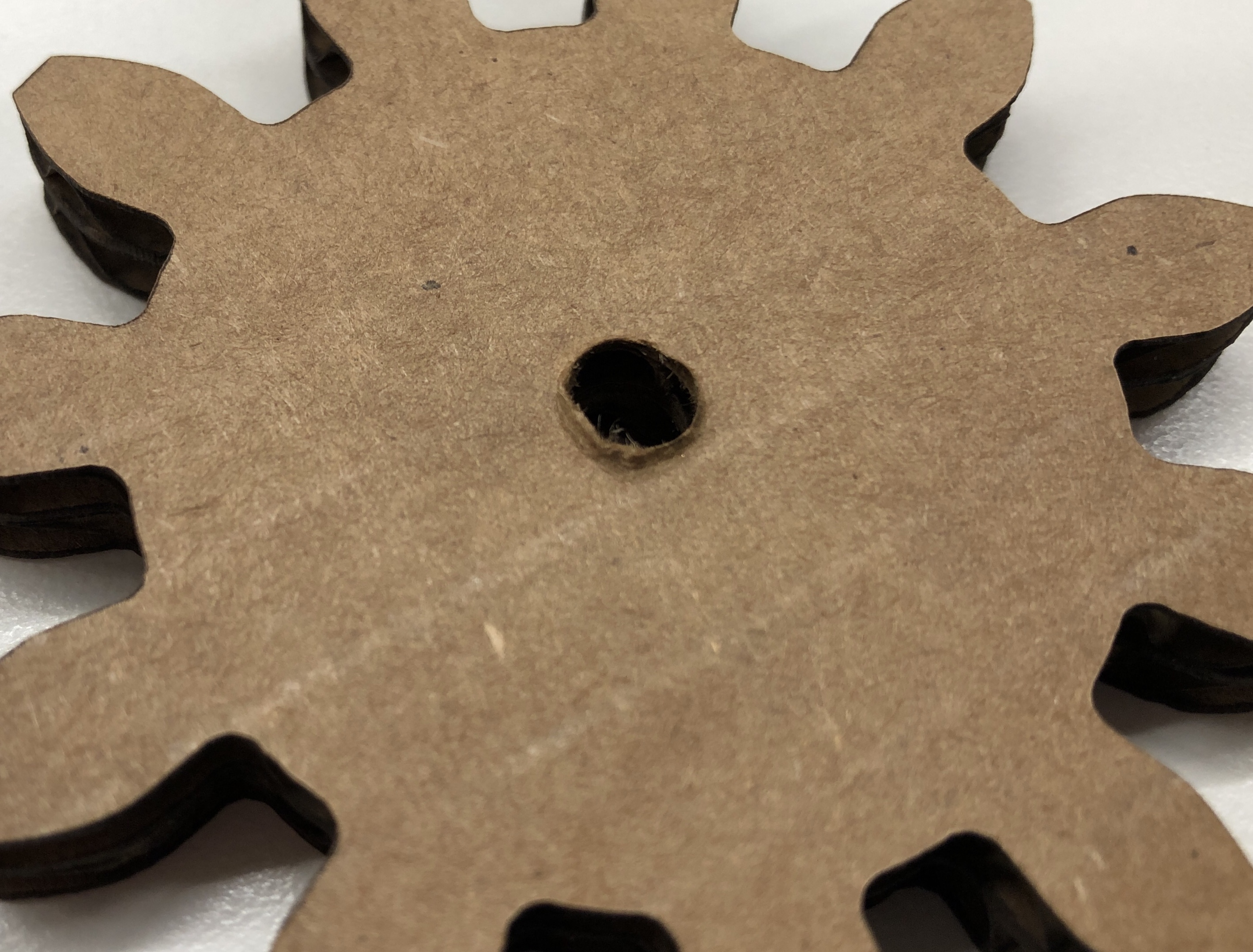
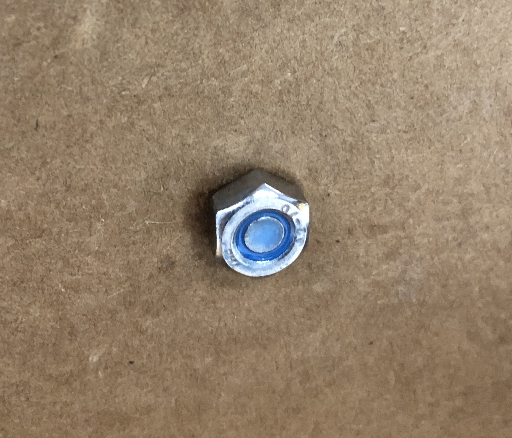
Unfortunately, there were two problems with continuous motorized operation: 1) the screws tightened (or loosened) over time from the rotation, and 2) the parts eventually seized once the screws were too tight, causing the powerful geared motor to wallow out the keyed hole in the cardboard drive gear fixing it to the motor shaft. With a round hole the motor shaft was able to spin freely without driving the gear—not good.
To avoid these issues, I applied Loctite threadlocking adhesive to the screws so the nuts would not move mover time. I also re-created the motor drive gear out of wood so the motor would be less likely to enlarge the mounting hole. I also added metal washers between the gears and the base plate to decrease the amount of contact and friction. This all worked well! A collar/spacer around the screws (or a proper bearing) would be even better.
The Fusion360 file for the Geneva drive can be found here. YMMV duplicating it since the final sketch to cut the parts was the product of a fair number of extrude-project-composite operations from the parametric starting sketch.