Charlieplexing LEDs
For this week's assignment on output devices, I wanted to try something I learned about from Rob's website but had never done before: charlieplexing.
Charlieplexing is a way to control P*(P-1) LEDs using P digital IO lines on a microcontroller. In short, it multiplexes multiple LEDs using relatively few pins. It takes advantage of the fact that microcontroller pins can source current, sink current, and be placed into a high-impedance state (effectively disconnecting them).
 Pins    LEDs
   1       0
   2       2
   3       6
   4      12
   5      20
   6      30
   7      42
   8      56
   9      72
  10      90
  20     380
  40    1560
   n   n(n-1)
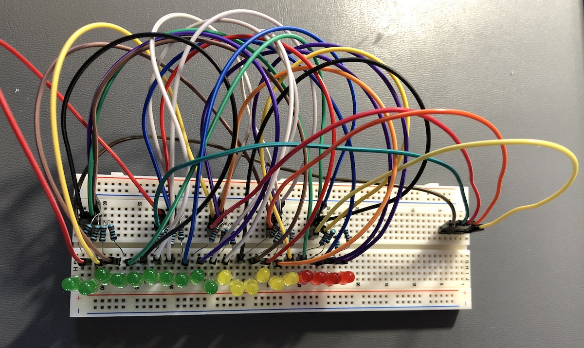
I decided to control an array of twenty (20) LEDs using five (5) digital IO lines on an Arduino Uno. This is more LEDs than can be controlled by the Uno if each LED were given its own pin.
The wikipedia page on Charlieplexing is not the most straightforward way to learn about how to construct a charlieplexed circuit, though it does cover nuances like unbalanced circuits and different ways of incorporating current-limiting resistors.
I found patent US4319227 most helpful for understanding charlieplexing, in particular the figure on the first page:
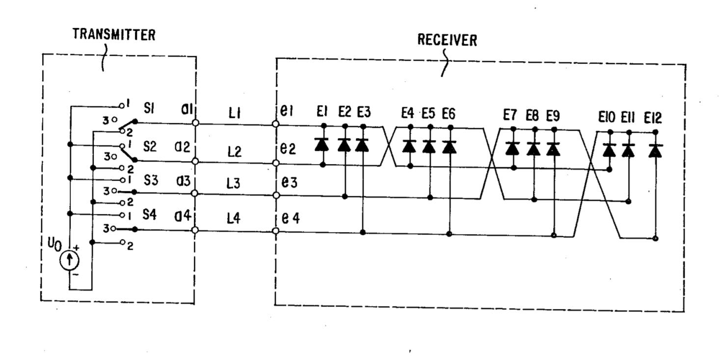
My circuit is the same, except extended to 20 LEDs.
Described in prose, charlieplexing is actually quite simple: to control N LEDs, P = 1/2 (sqrt(4N + 1) + 1) pins are needed. The LEDs are divided into P groups of N/P LEDs. The anodes of all of the LEDs in a group are connected to a particular IO pin via current-limiting resistors (or via one current-limiting resistor if the LEDs have balanced current draw). Then the cathodes for the group are scattered to connect the other IO pins, excluding the IO pin to which the anodes are connected. This is repeated for all of the groups of LEDs.
With a 5V supply, LEDs with a voltage drop of 1.8V and desired current of 25mA, each needs a resistor of ~128 ohm.
V = I*R
(rearranging)
R=V/I
R=(5V-1.8V)/(0.025A)
R=128 ohm
The closest resistors I had on hand were 120 ohm, which worked fine.
Since the LEDs I'm using are not identical, I put a resistor in series with each one in case the current is unbalanced across different paths of the array.
In my circuit I also added a 10K potentiometer between 5V and ground, with the wiper connected to A1, so I could scroll through the full range of LEDs. I also added a piezoelectric element as a contact mic as described on Rob's page, connected to GND and A0 (which is itself connected to 3.3V via a 1M-ohm resistor).
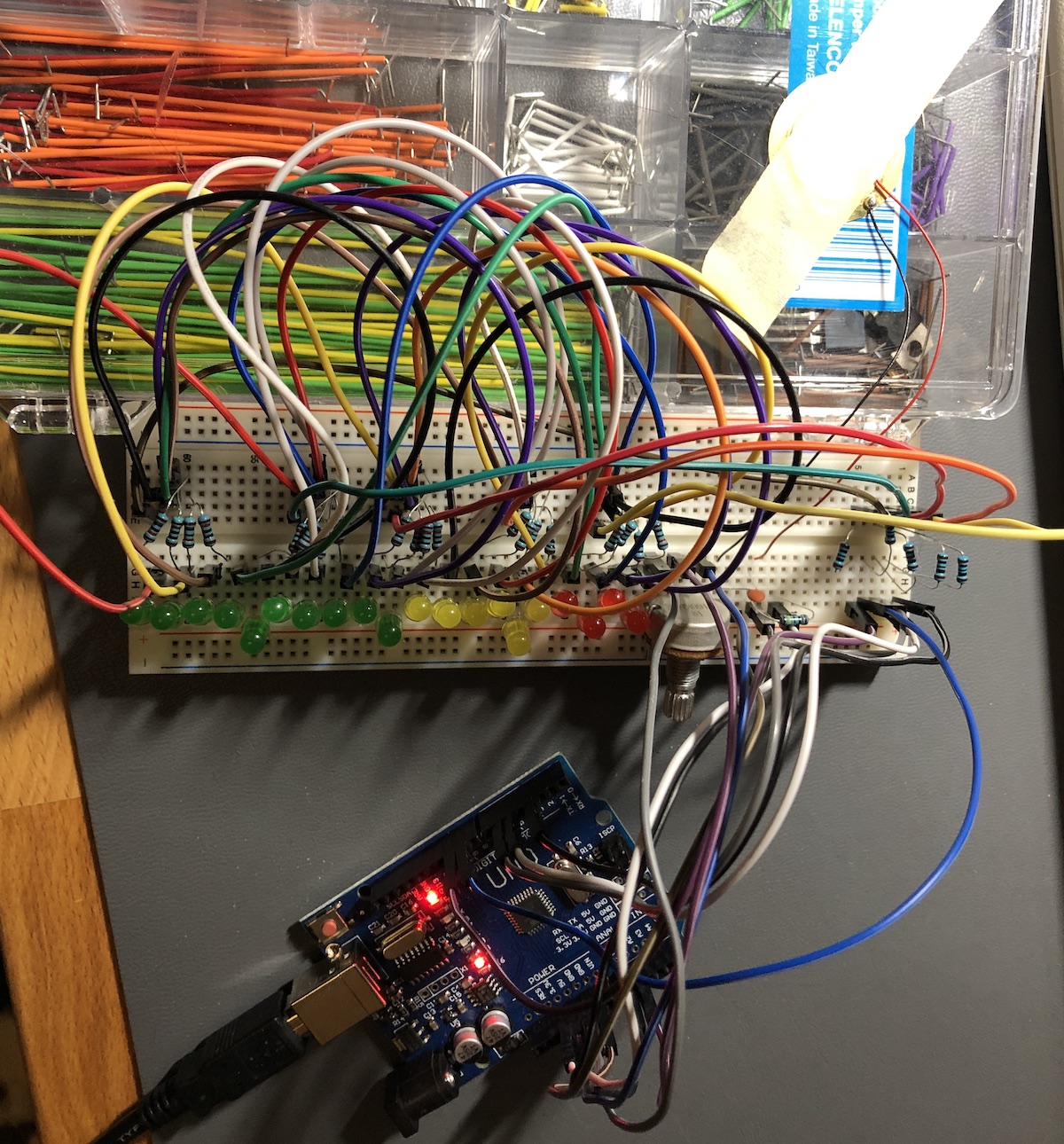
I perused the web to get ideas for how software control is handled for charlieplexed LED arrays, and adapted one particular example to my use case. It worked well!
I attempted to smooth out the transitions between states by PWMing the highest-value LED to fractional values between steps, however it was only marginally more smooth because the scan LED scan frequency is near the PWM frequency of the Arduino Uno. I found the array looked best without PWM.
The code can be found on GitHub: