3D Printing
A simple model: spinning toy top
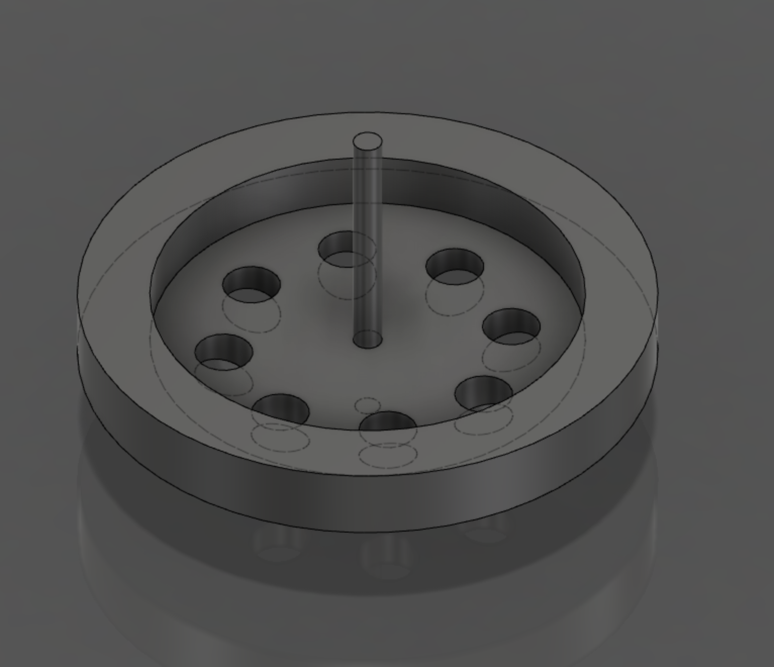
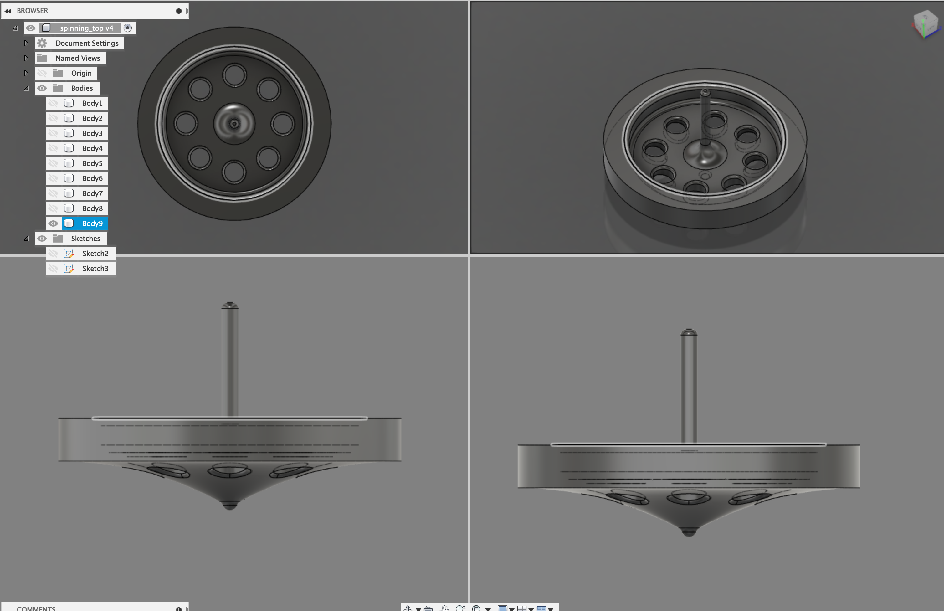
Design
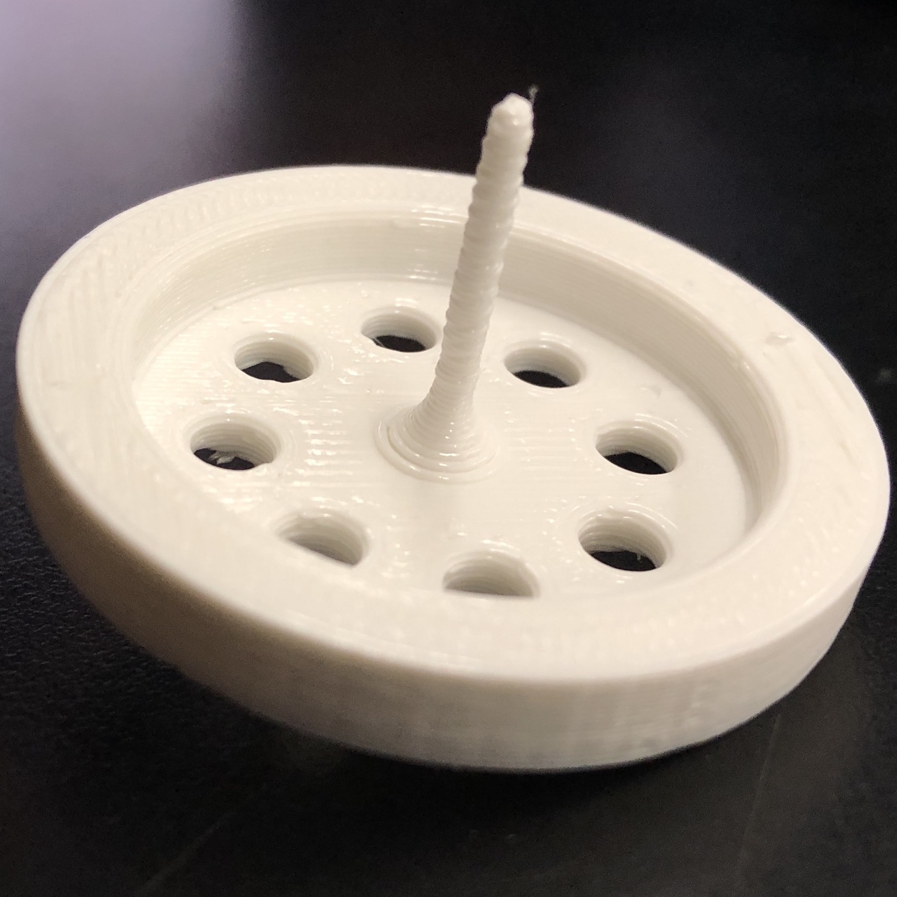
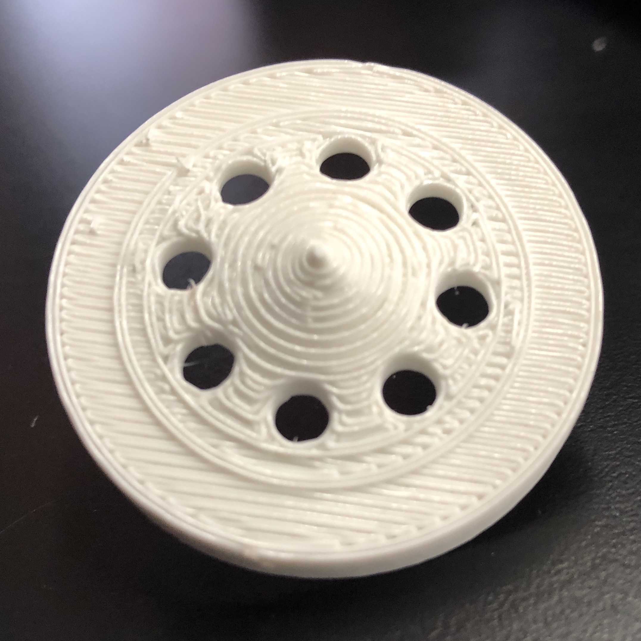
To become acquainted with 3D printing at the lab, I modeled a simple spinning top toy in Fusion 360. It's a design that would be impossible to make on a laser cutter and relatively difficult to make using a CNC mill (multiple steps, tricky work holding) but as designed it could be produced on a lathe with multiple operations and a separate drill step (though the thin spindle may be difficult to turn).
The design file for this object is available here (stl).
Slicing
I converted an exported STL file of the model to gcode that will instruct the printer how to move to produce the part. This conversion slices the object into layers. I used PrusaSlicer for this, configured to add supports (since the top has an overhang) and operate at draft quality (0.3mm layer height).
Printing
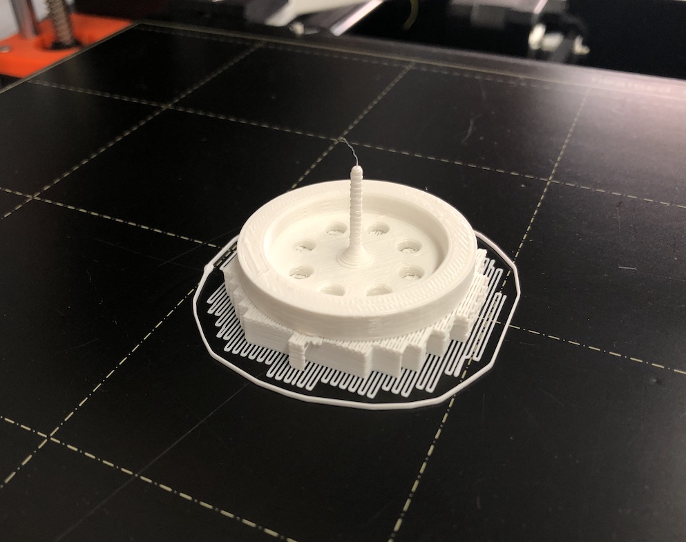
I printed the model on a "fused filament fabrication" printer, the Original Prusa i3 MK3.
I pre-heated the printer (extruder and build platform) to temperatures suitable for printing in PLA.
Almost immediately on starting the job the first layer started to de-laminate from the build platform. There were fingerprints on the build platform, so I guessed that oil from human skin was preventing adhesion of the first layer. I stopped the job, cleared the plastic that had been deposited, and cleaned the build platform with isopropyl alcohol. I restarted the job and it worked perfectly.
3D reconstruction using photogrammetry
In addition to designing parts from scratch, I'm interested in using 3D modeling to design parts that mesh well with things in the real world. One way that is accomplished is by using an expensive 3D scanner to take measurements of real-world objects and reconstruct them as accurate digital models. 3D scanning can be done in a few ways: stereoscopic imaging (like our eyes), time-of-flight capture of light emitted in a prescribed pattern (see LIDAR), structured light, or photogrammetry, a approach to take measurements using ordinary photos. Photogrammetry was historically used to gather measurements from aerial images taken by well-characterized cameras. It is increasingly used to build 3D models using an inference-based computer vision approach that matches features co-occurring in ordinary photographs captured from multiple angles and estimates the original camera angles from which the photos were taken. After this, reconstruction happens similarly to stereoscopic reconstruction, with refinement from many more photos.
I decided to give the open-source Meshroom software a try for to "3D scan" a physical object using photogrammetric reconstruction.
The object
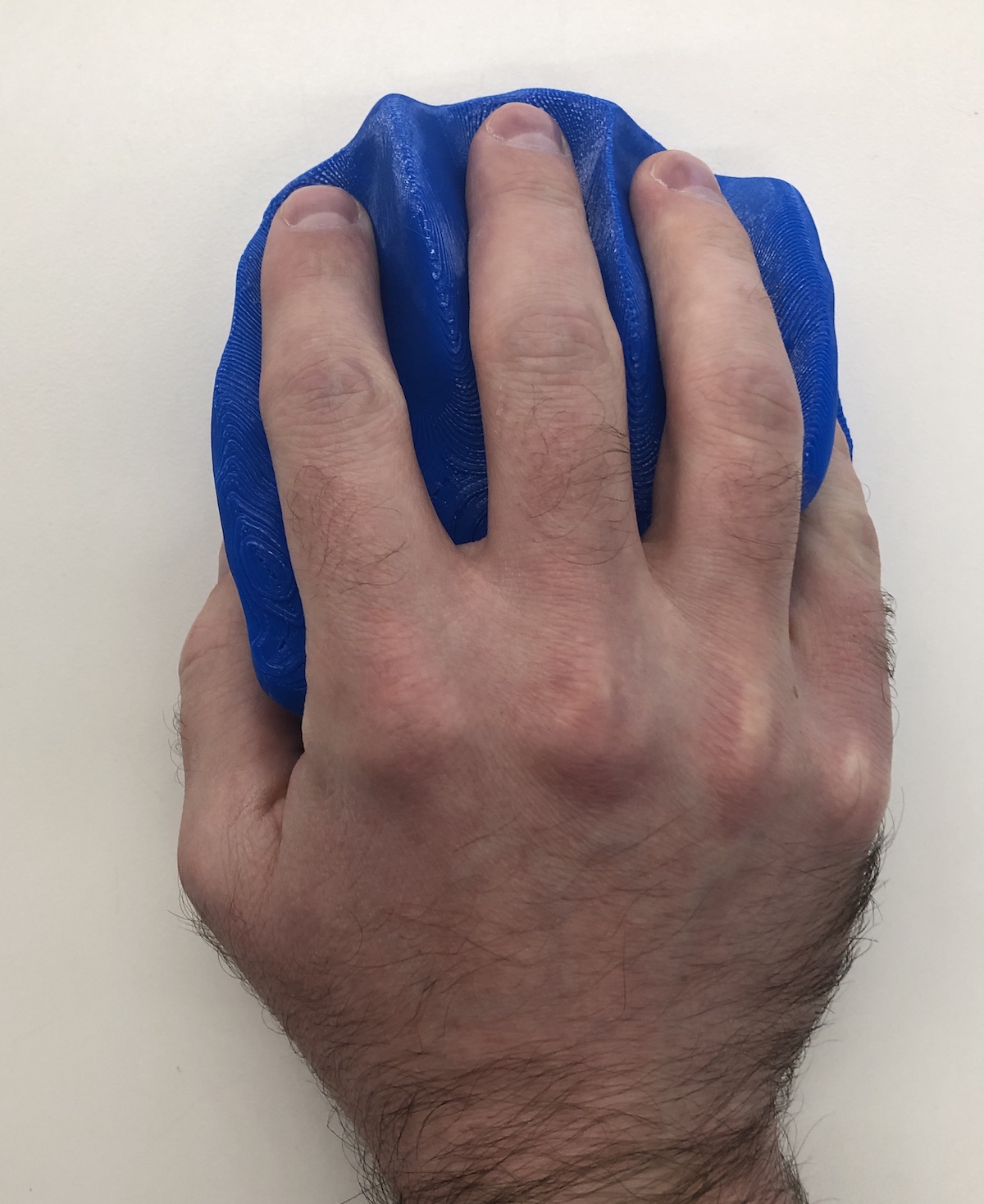
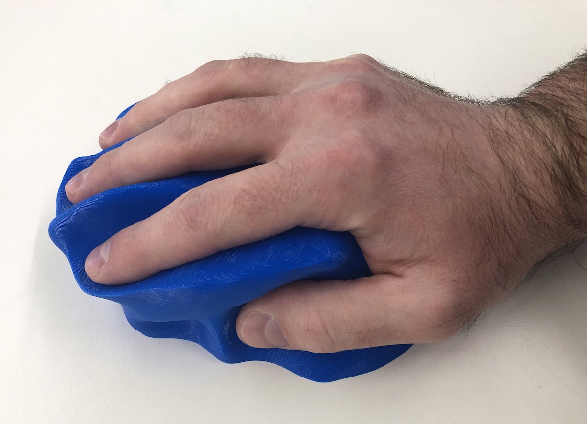
To kick the tires on Meshroom I wanted to scan a shape that would be difficult to measure by hand or model directly in software. That meant organic curves, difficult overhangs, and features that do not repeat or align in any particular way. I chose to model a shape that could form the basis for a custom-fit ergonomic computer mouse.
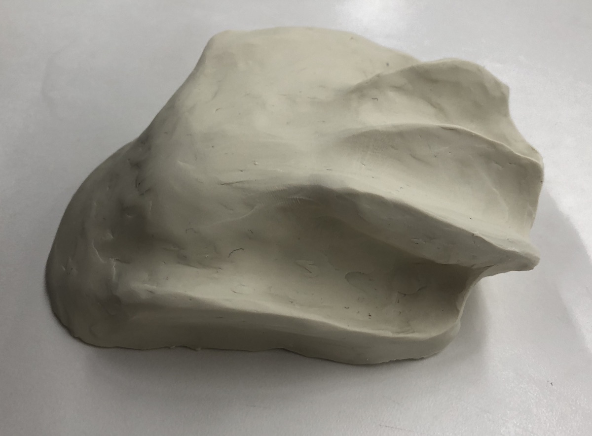
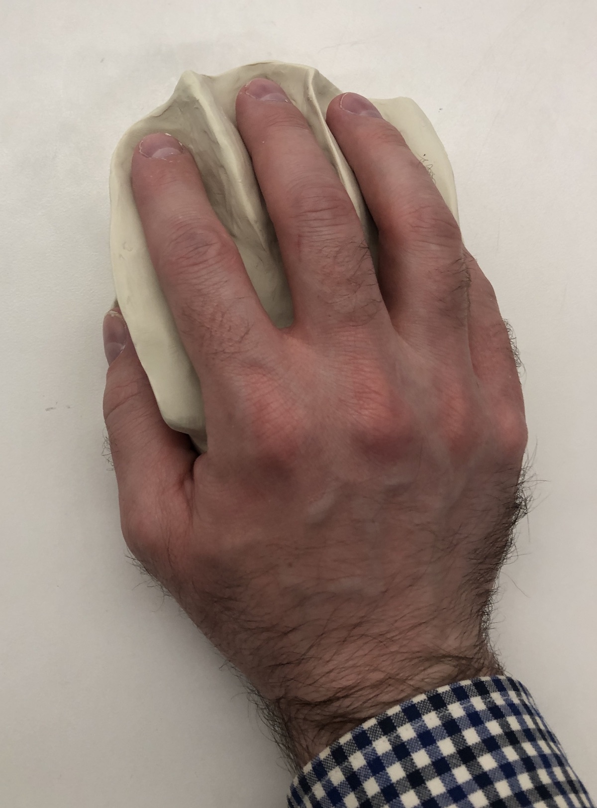
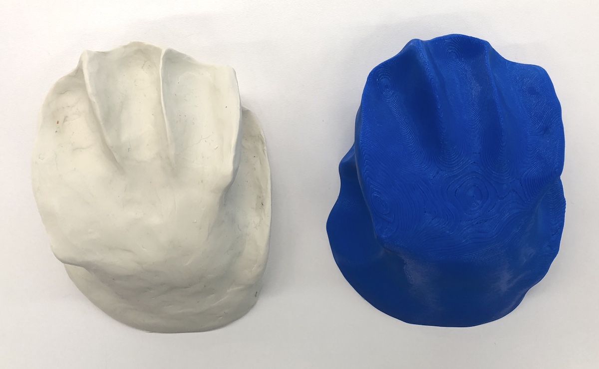
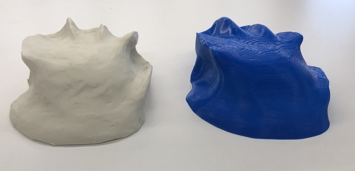
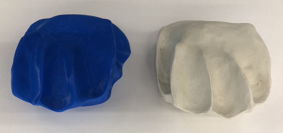
I made my object by sculpting it out of modeling clay to fit my hand. This took a while as I had never worked with clay before. I found it most challenging to smooth the surface, but irregularities present may have been helpful for digital reconstruction by serving as control points the algorithms like SIFT included in Meshroom.
Setting up for photogrammetry
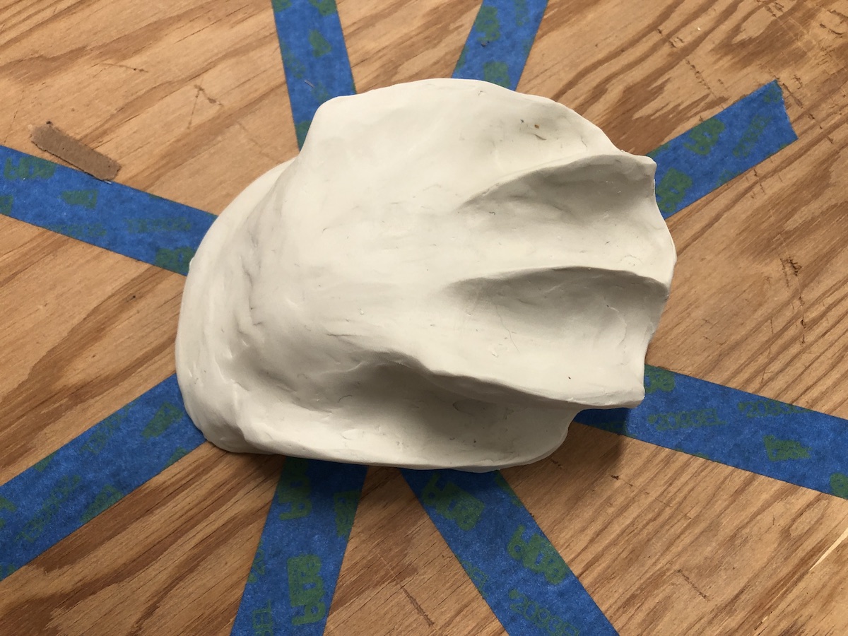
In order to get good data out of photographs, features visible in one frame need to carry over and appear in other frames. That can include features of an object itself, but also of the surface it is on or its background. To make it easier to scan my "mouse" model, I placed it on a plywood turntable available in the lab. The turntable already had irregular strips of blue tape to serve as references to assist later reconstruction. I then proceeded to take 175+ photos of the object from as many angles and distances as I could, while maintaining approximately equivalent exposure across the photos. For some of the photos I spun the turn table, for others I walked around it. I used the same camera for all of the photos, the rear-facing camera built in to my iPhone 8. The iPhone includes metadata in each photo including the focal length, aperature, and exposure settings of the camera when the photo was taken. Having the information about the optics helps Meshroom estimate the perspective of each camera.
I've learned that in the top-down photos taken for photogrammetry it is probably helpful to include a ruler or other fiducial for scaling the end result. More on that later.
Creating 3D meshes using photogrammetry
I loaded all of my photos into Meshroom, and clicked "start". Virtual "cameras" started to appear in Meshroom's preview pane to indicate where it has estimated the photos were taken relative to other photos in the set.
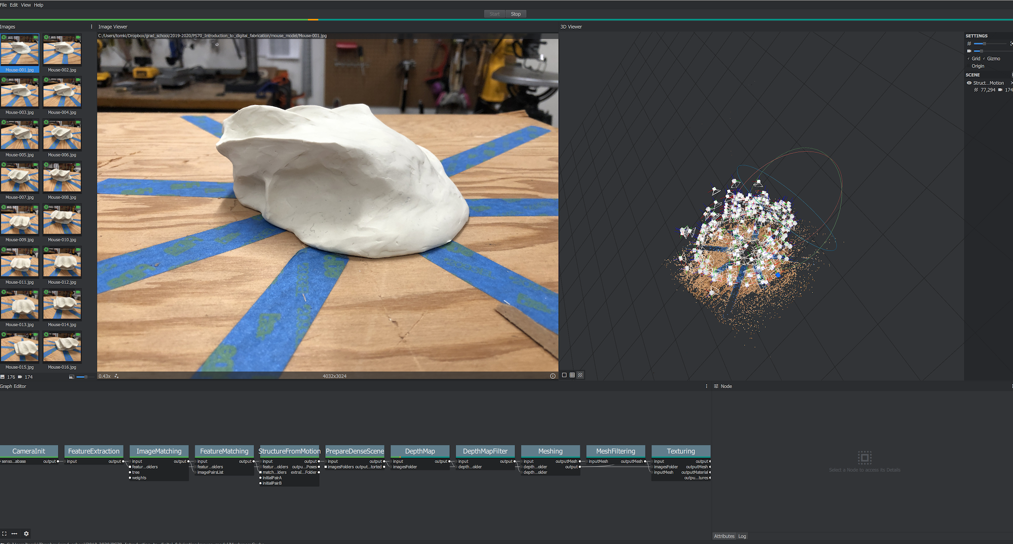
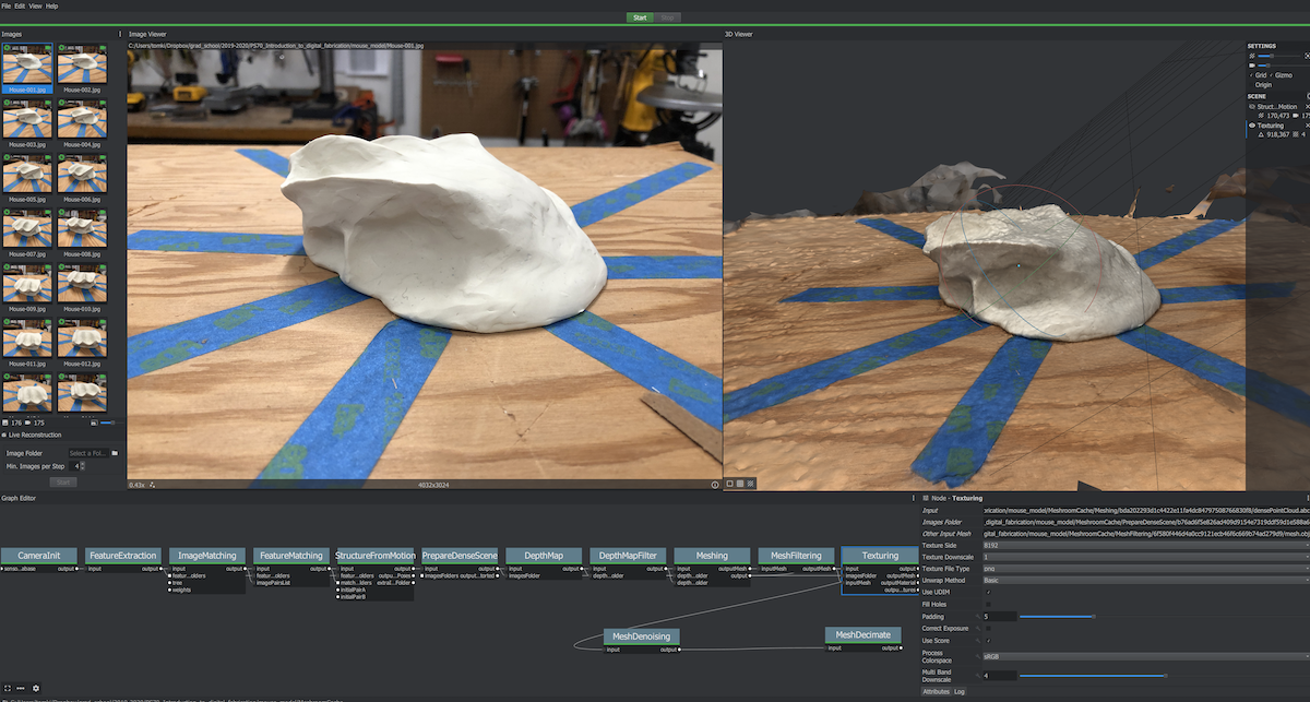
After running for quite a while, Meshroom finished computing camera positions ("structure from motion") and provided an option to texture the model. This created a 3D mesh of the scene, which I viewed using Rhino 6.
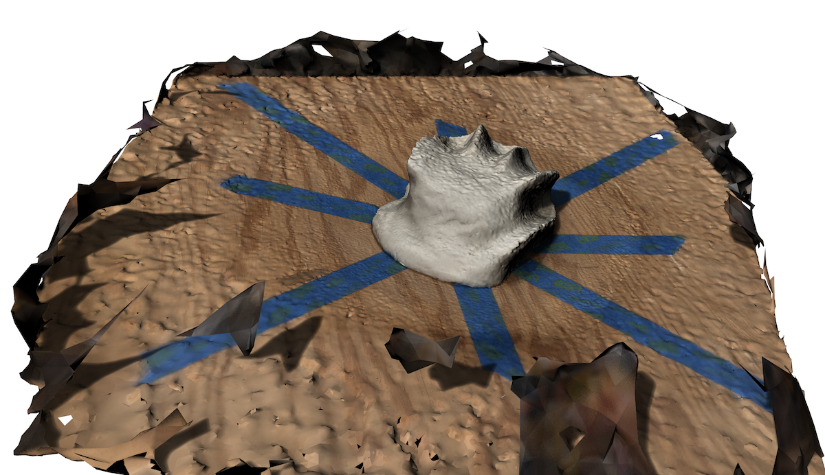
The mesh produced was fairly "lumpy" though, with irregular bumps and divots appearing on the virtual surface of my clay model.
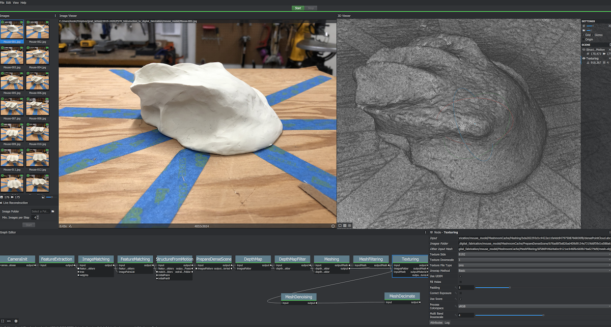
The mesh created by this process was also large in file size, about 63MB, and complex: about 500,000 triangles. Meshroom provides an option to simplify the mesh by adding a step to "decimate" the mesh. The process Meshroom uses to reconstruct a scene is exposed as a visual programming network of steps. Right clicking on the network pane allows new steps to be added. Connecting the output of the reconstruction to a "decimate" step reduced the size of the mesh considerably, to about 16MB, while keeping the appearance about the same.
The mesh was smaller but still lumpy. Meshroom also provides a "denoise" step that smooths the texture of the mesh. I inserted this between the output and decimation steps, so the denoising step would have a detailed mesh to work with.
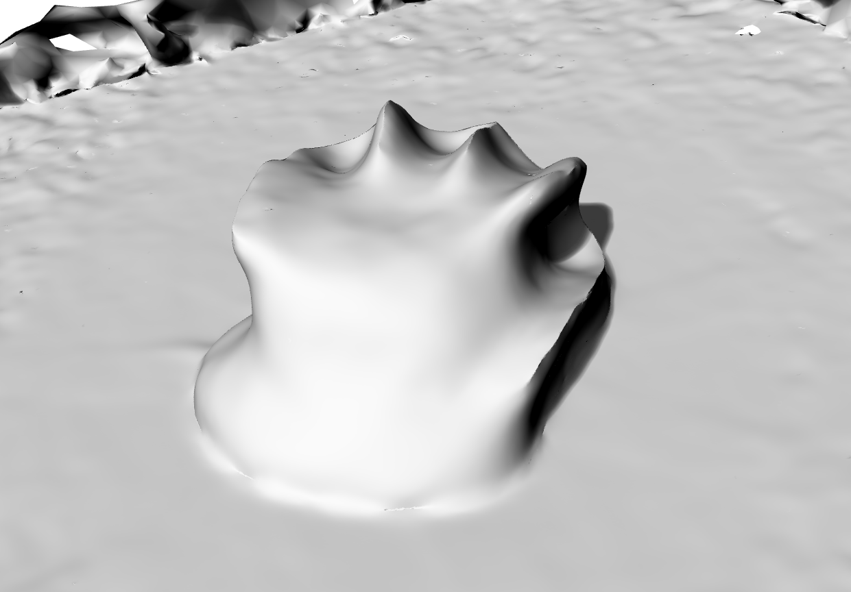
Unfortunately, the resulting mesh looked a bit too smooth (lacking detail), which I suspected was due to the difficulty of mapping texture to the smooth and constant-color surface of the clay. It would have been beneficial add texture to my model in the physical world to make reconstruction easier for Meshroom. For some objects that can be done by irregularly dusting them with powder such as talc or cornstarch. Those powders would not show up well on the white clay I used. I could have applied something like carbon powder or spray paint, but I wanted to avoid contaminating the clay so it could be re-used by someone else.
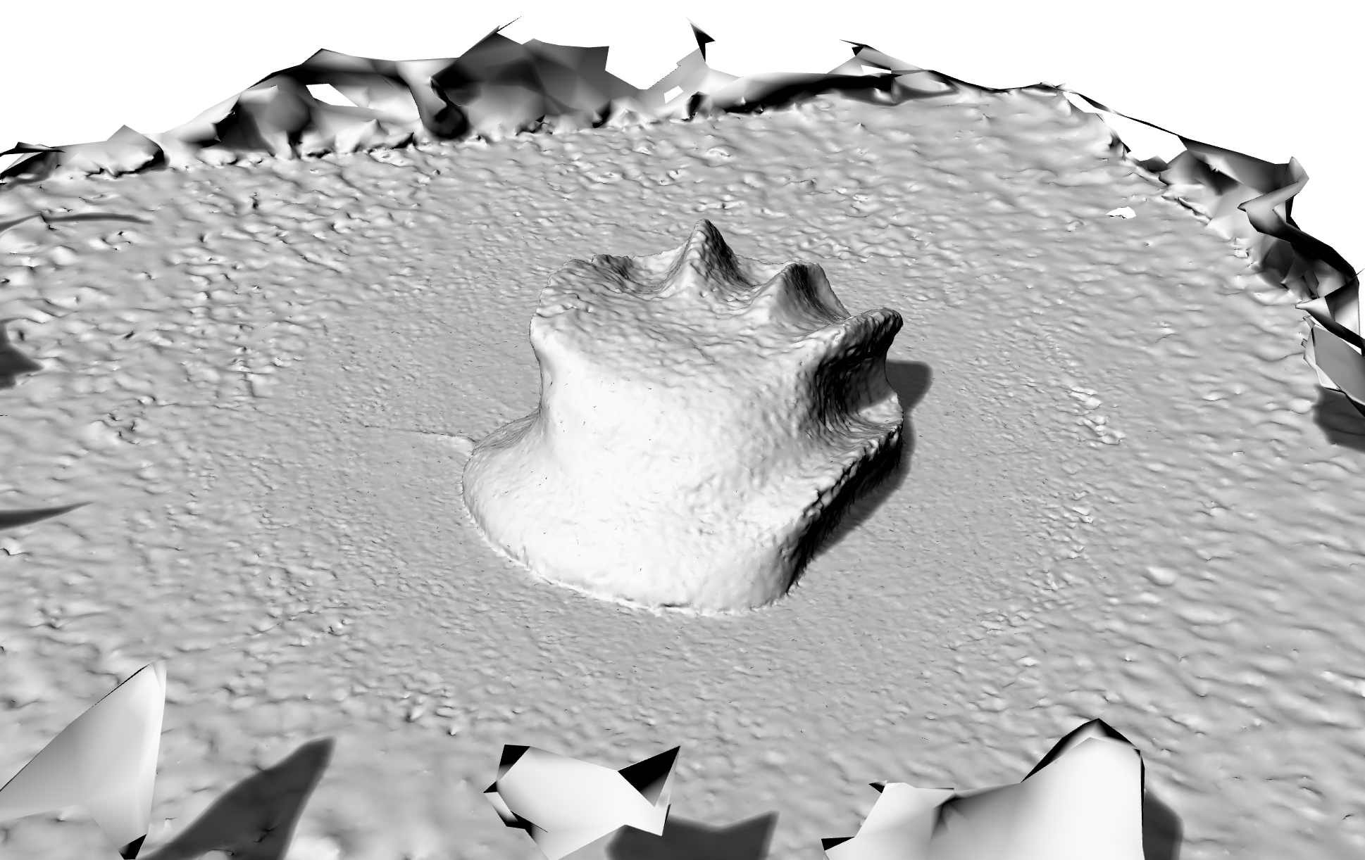
After reading about Meshroom online, a few threads suggested texture quality could be improved by increasing the quality/resolution of the feature extraction step in Meshroom so more of the image data would be used for mapping. I changed it from the default value of "medium" to "high" and re-started Meshroom's reconstruction of the scene. With the higher quality setting, reconstructing the scene went from taking about an hour to an over-night process. That's on a machine with a 24-core CPU, 128GB of RAM, and a modern GPU with 8GB of memory.
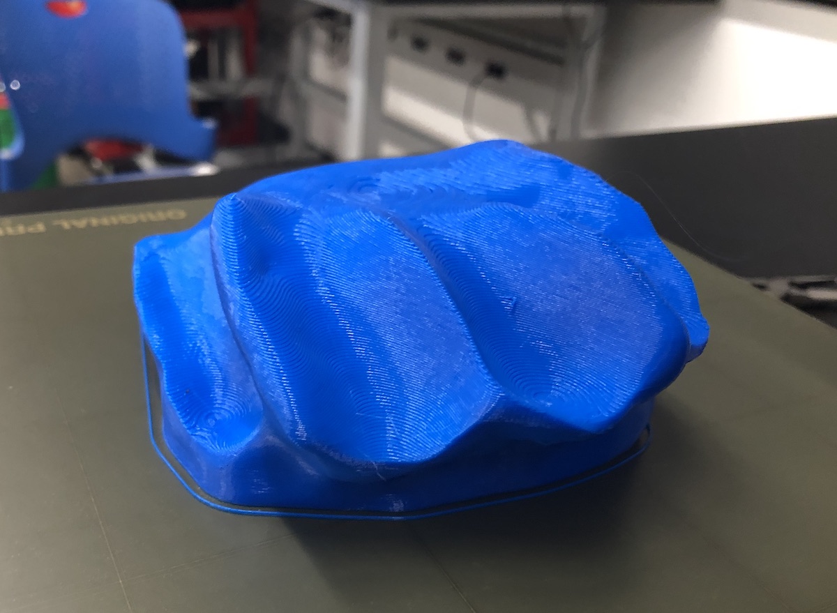
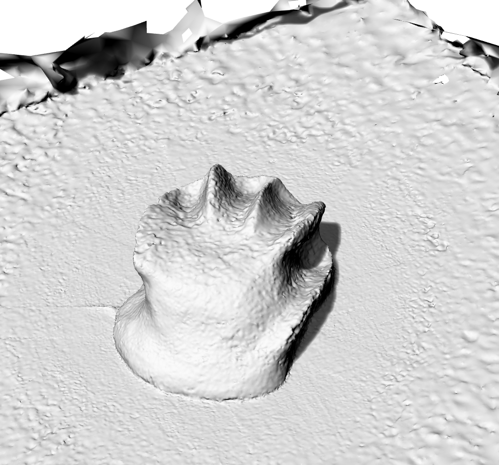
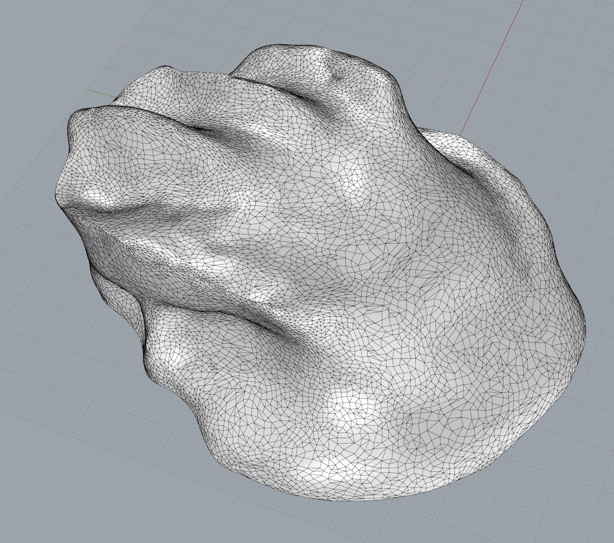
The resulting mesh looked closer to the original model (which had some lumps) before any smoothing:
Post-processing of meshes
The resulting mesh looked good but included more than just my clay model; it also had the turntable on which it was placed. To work with and print the model the turntable surface has to be removed. The mesh is also open on the bottom (since no photos exist from that angle), and the model needed to be closed after trimming away the table.
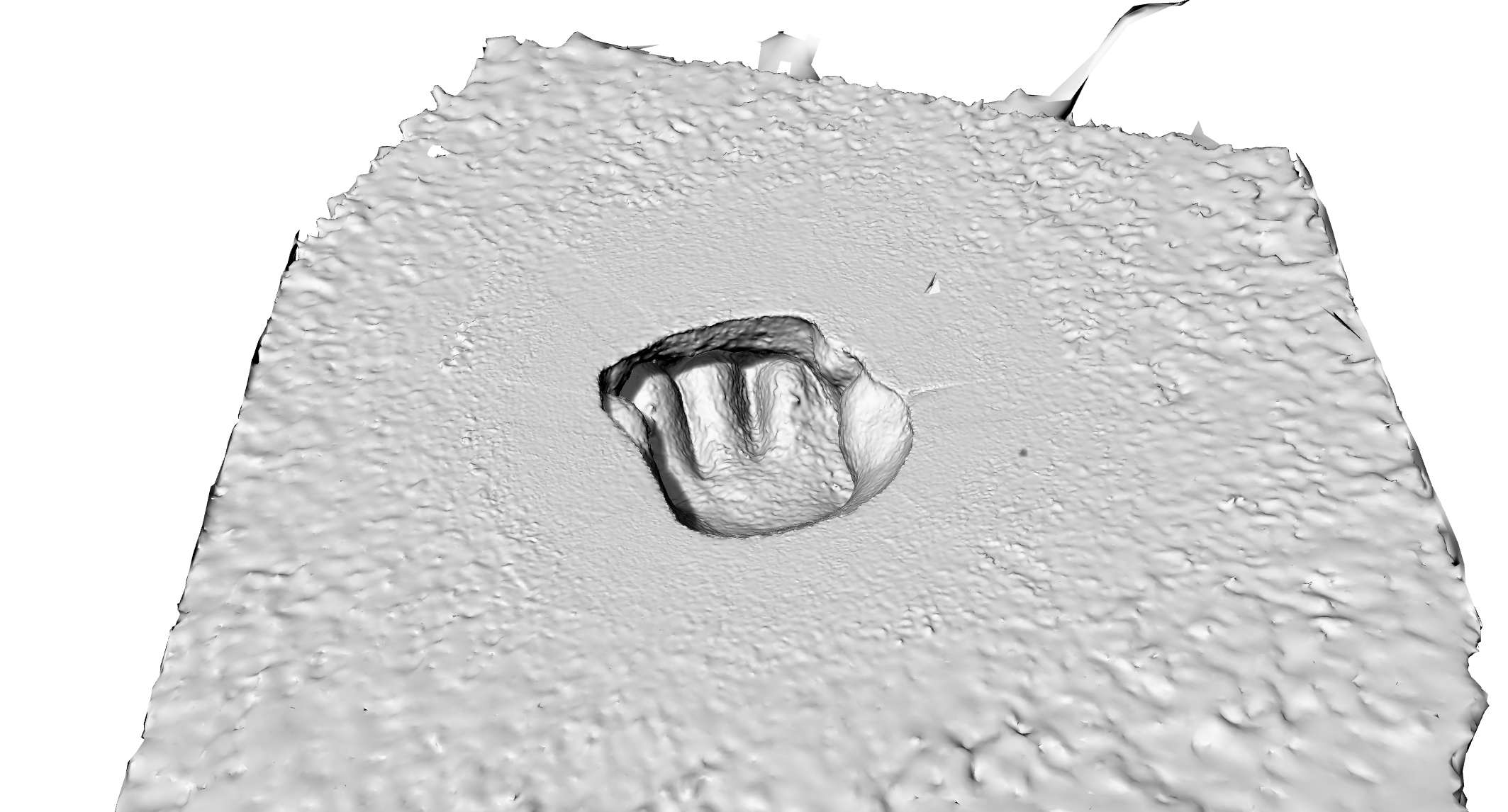 (bottom of lumpy mesh shown here)
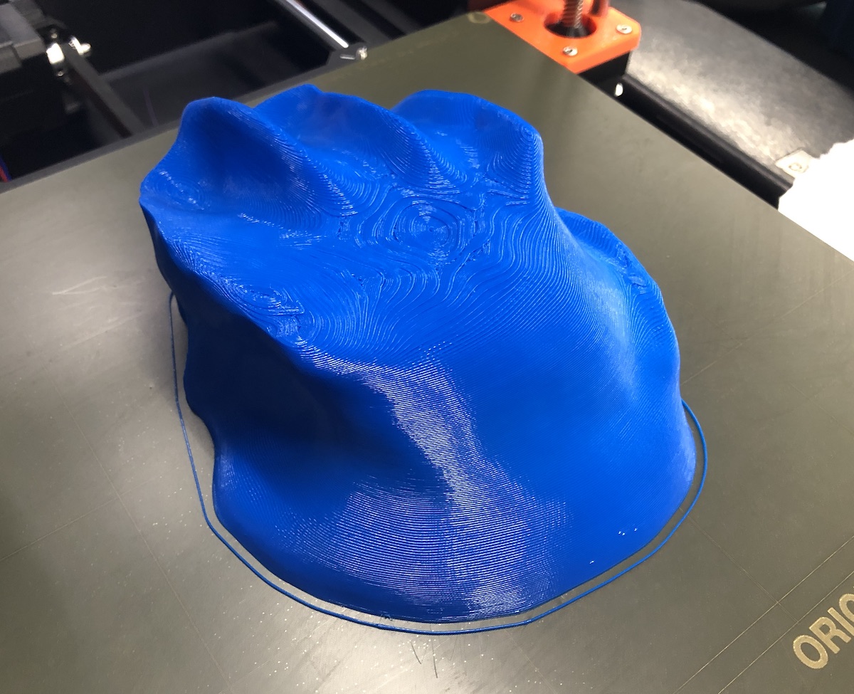
I refined the mesh using a combination of Rhino3D and Microsoft's 3D Builder. I used Rhino to trim away the mesh faces making up the "surface" of the table my model was positioned on, and 3D builder to repair and close the mesh. I also used Rhino to reduce the number of faces in the mesh by about 75%. The resulting mesh looked acceptable, so I decided to print it. It will not be a functional computer mouse, of course, but I wanted to check the geometry of the scan before going through the effort of adapting the model to have movable buttons and space for electronics. This was also primarily an exercise in learning to use photogrammetry software to "3D scan" a difficult object, so actually turning the model into a mouse may be reserved for the future.
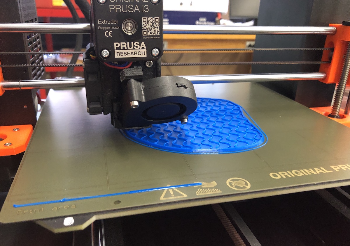
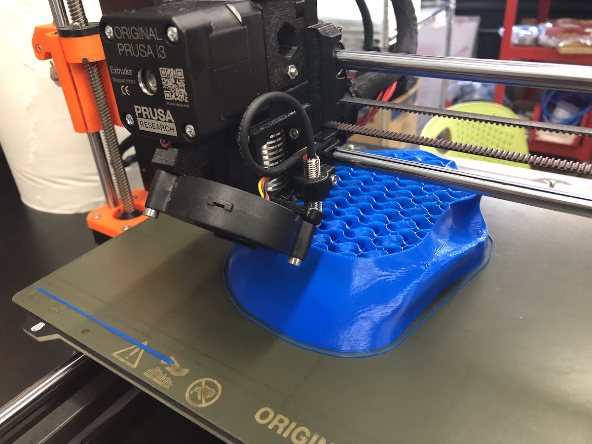
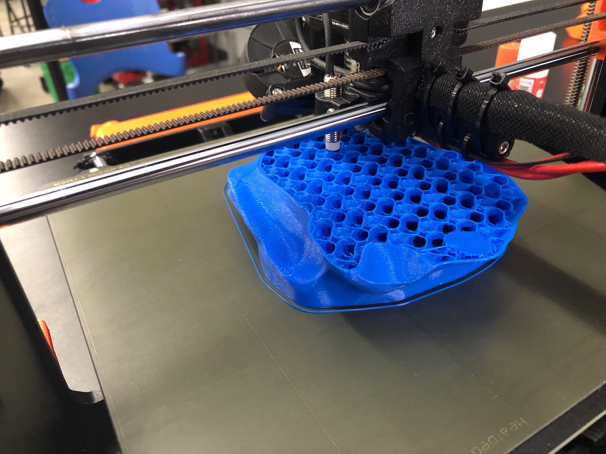
Printing the model
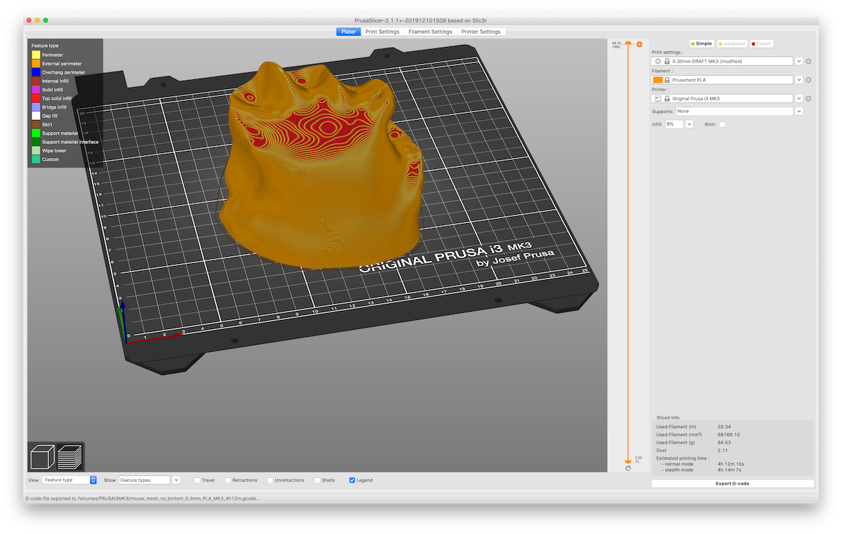
I learned at this point that Meshroom photogrammetry cannot correctly assign scale to the meshes it creates. The shape of my model may be correct, but its scale was far too small. Next time I use Meshroom I will place a ruler in-frame to record scale. This time I rescaled my model in PrusaSlicer to have a maximum length equal to a measurement of the physical model I sculpted.
I sliced the model using PrusaSlicer 2.1.1+, using the "DRAFT" 0.3mm layer height setting to save time. I specified 8% gyroid infill, and concentric fill for the top and bottom layers. With these settings the print time was estimated at about four hours.
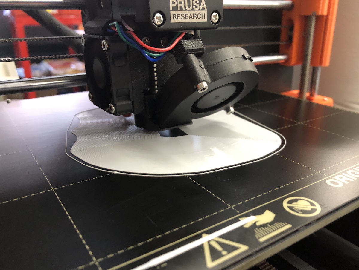
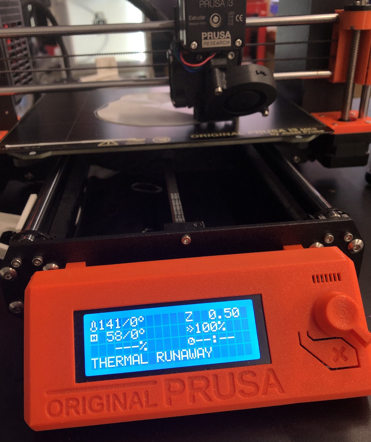
Unfortunately, the printer stopped halfway into the second layer, with a message alerting of "thermal runaway". From the Prusa website I learned this is a failsafe state and the printer is not likely to imminently destroy the lab in a noxious conflagration, but for safety I allowed the hotend to cool, switched off the power supply, and posted a warning not to use the printer.
I started the job on a different printer and alerted Rob and Nathan of the issue.