Anemometry Sensors
For this week's assignment I wanted to build two different sensors for measuring wind speed, also known as anemometers. The first relies on the ability of moving air to carry away heat, the hot-wire anemometer. The basic principle behind its operation is that as airspeed increases more heat will be carried away from the sensor. The sensor itself is something whose resistivity varies with temperature, such as a thin wire of pure tungsten or platinum (both have a positive temperature coefficient [PTC]), or a a thermistor (available in NTC or PTC). The change in resistivity can be measured several ways and can be related to the airspeed seen by the sensor.
The second type of anemometer I wanted to make uses differential air pressure to determine airspeed. This requires two components: a probe to sample the pressure of an airstream, and a device for measuring this pressure. For the probe, I wanted to make something like a pitot-static probe that samples an airstream with two apertures: one facing directly toward oncoming air (the pitot entrance), and one sampling the static pressure surrounding the probe. These two pressures can be compared to determine airspeed independent of air pressure, which is why the probes are used on aircraft to determine wind speed across their range of operating altitude. The density of air also varies with temperature, so a temperature sensor is typically included along with a pitot-static probe. To measure the differential pressure, I decided to use a water manometer with capacitive strips to measure the height of the water.
Kiel probe anemometer with capacitive sensing
As an alternative to a pitot-static probe design which only works well if well aligned with the direction of airflow, I decided to make a variant based on a Kiel probe, which uses a circumferential shroud to "re-align" the air stream and ensure the pitot entrance sees the total pressure of the air stream. Any point beyond the shroud entrance should see the full pressure. A NACA technical note shows the cross-section of a Kiel probe:
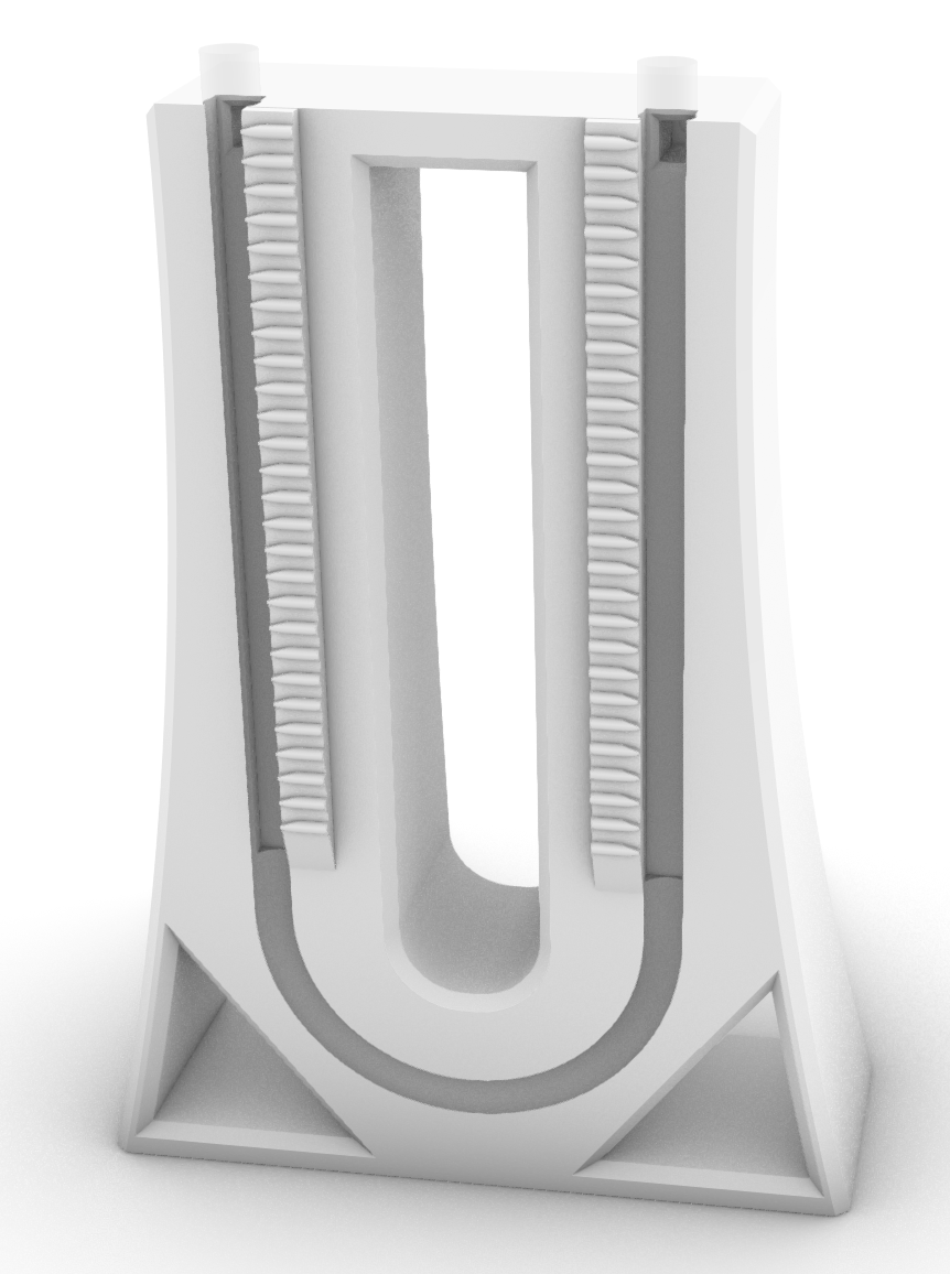
In my design, I wanted to combine the shield of a Kiel probe with static pressure inlets to serve as the reference pressure. I modeled a combined probe in Rhino, intended to connect to thin vinyl tubing (3/16" ID 5/16" OD):
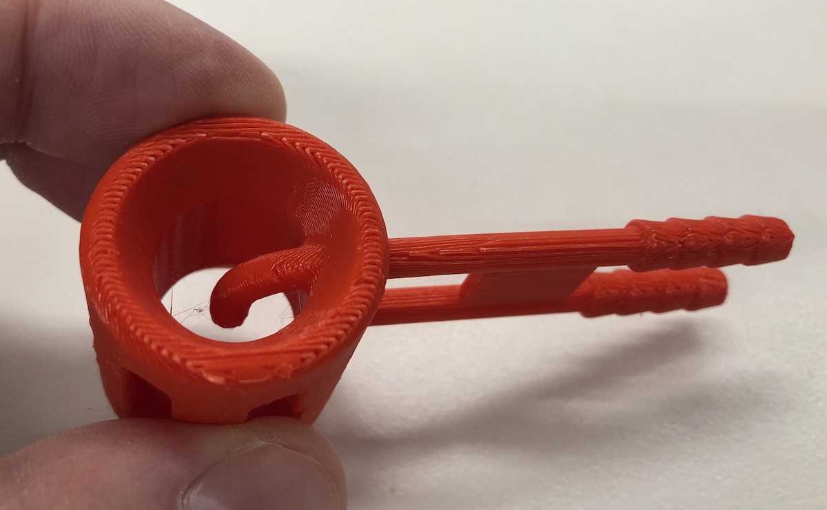
In this design, a circumferential series of ports allow for static pressure measurement around the exterior of the probe, while the probe in the center of the probe will capture the total pressure of the airstream. To model the host barbs I downloaded a STEP file for a suitable barbed fitting from McMaster-Carr and wire cut-away the parts I did not need.
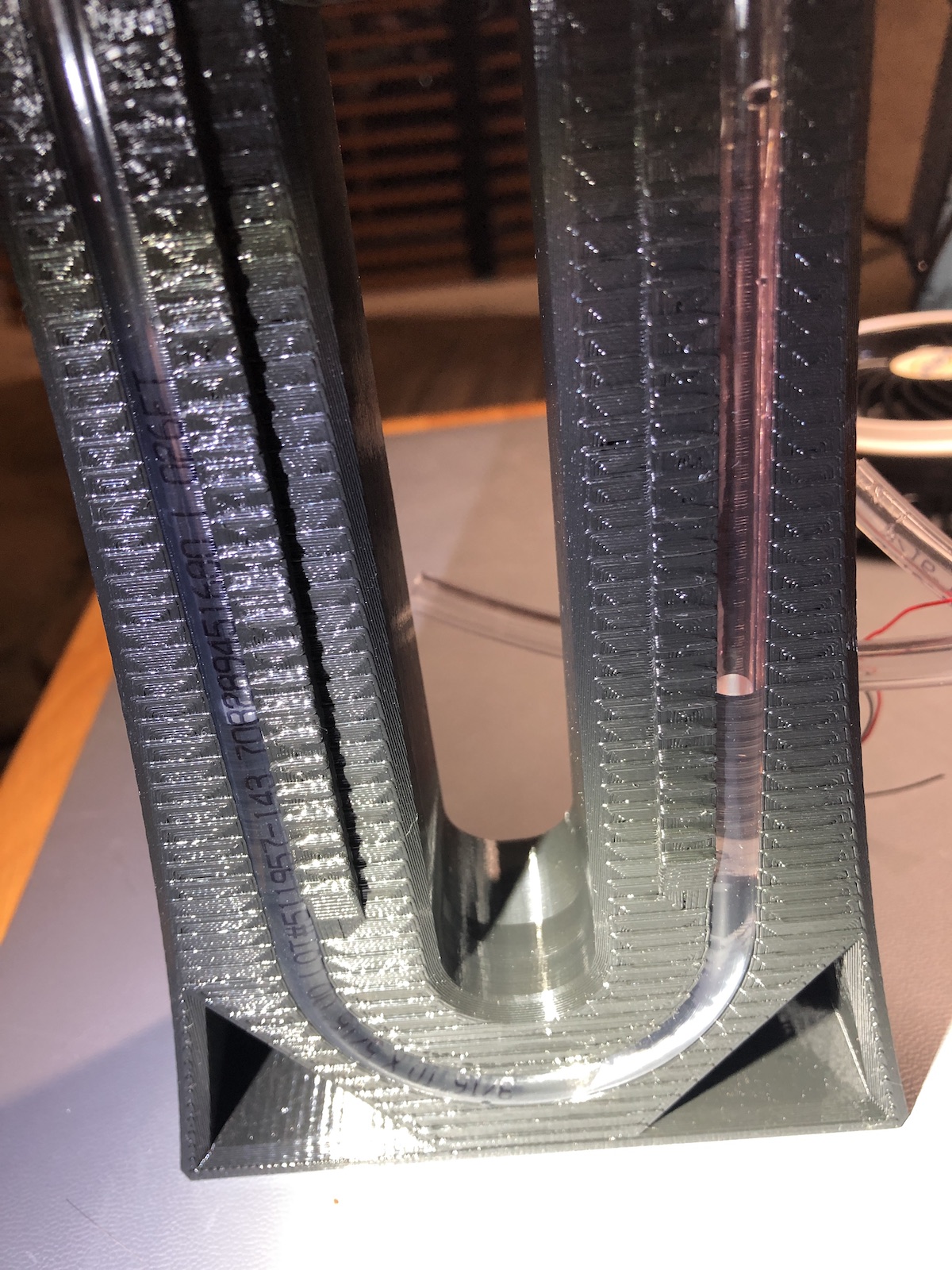
To measure the pressures sampled by the probe I designed a water manometer, with the goal of holding vinyl tubing captive while allowing for copper tape to be attached to measure the water height using capacitive sensing:
Files are available for the manometer and probe in 3mf format.
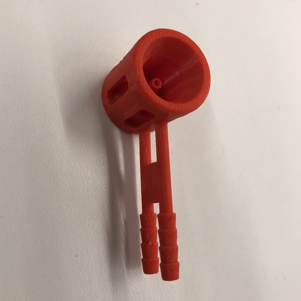
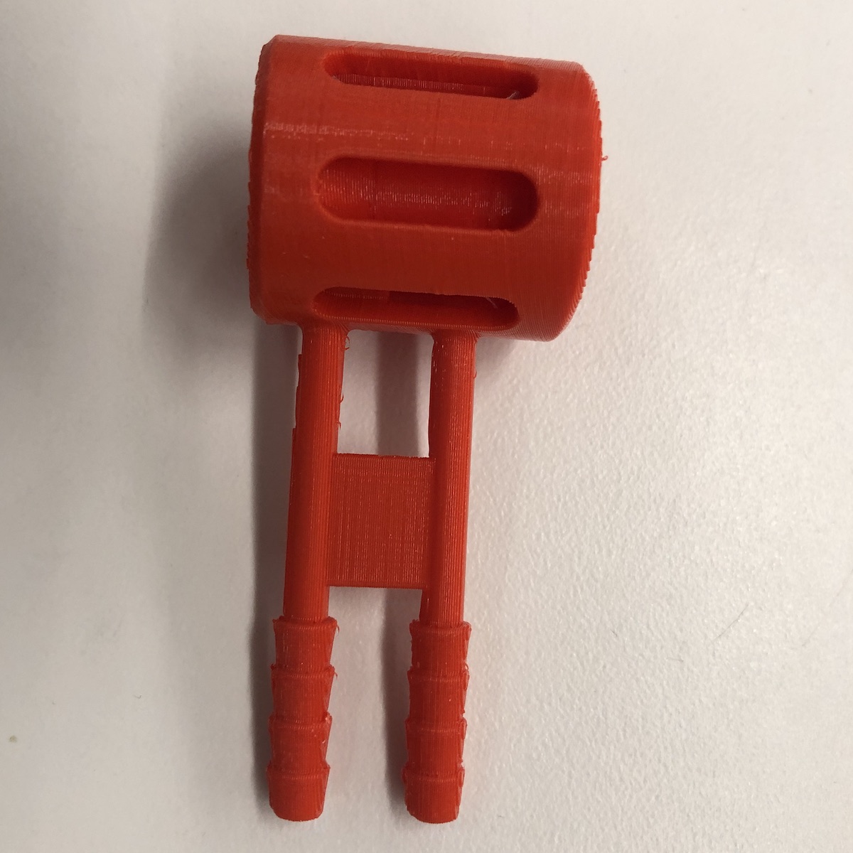
I printed the manometer and probe using a Prusa printer:
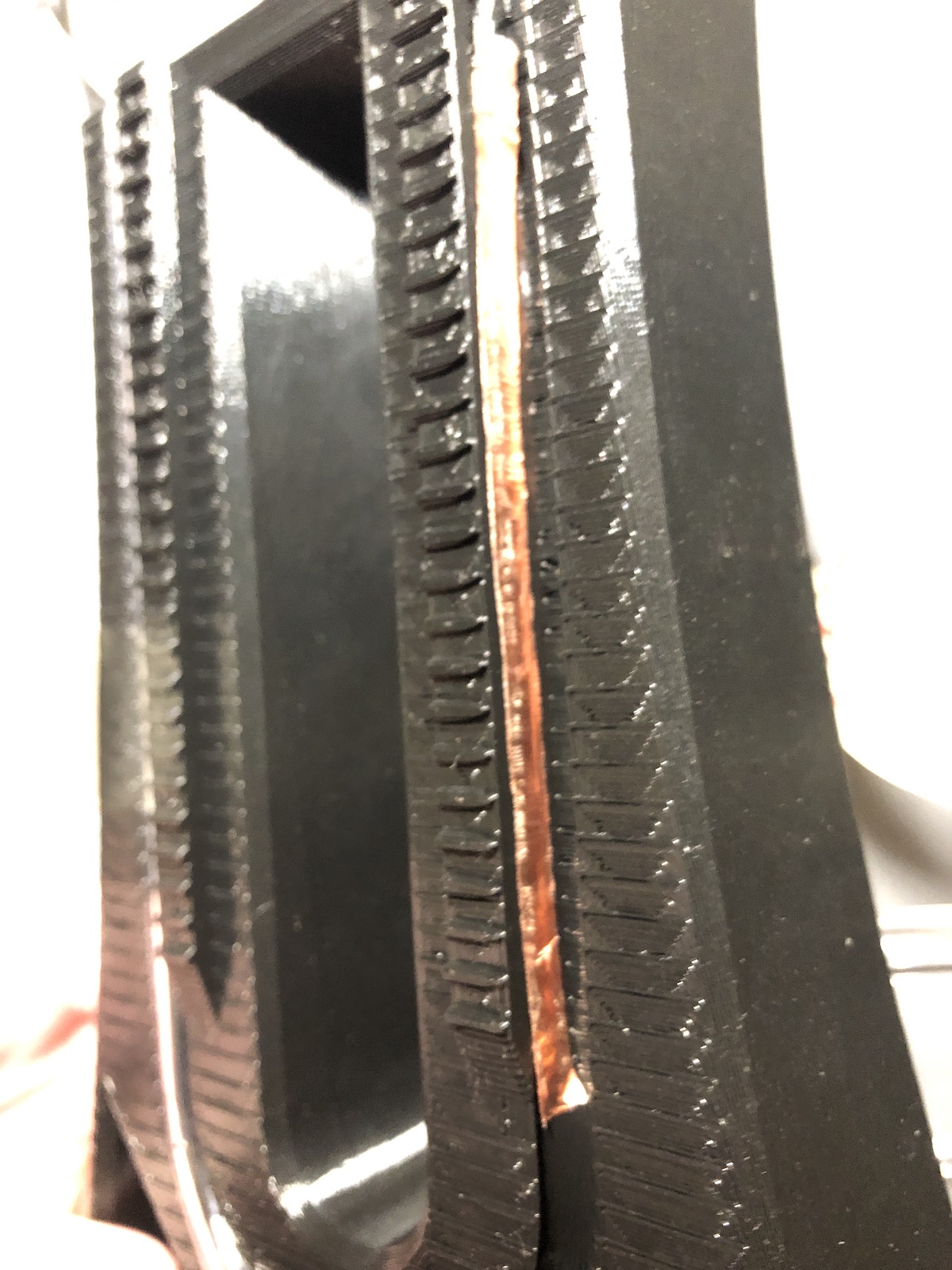
The manometer print holds vinyl tubing, making it easy to see the water level within. On one arm of the manometer I applied copper tape to the channel to serve as capacitive plates for sensing the level of the water.
The parts came together into a complete assembly.
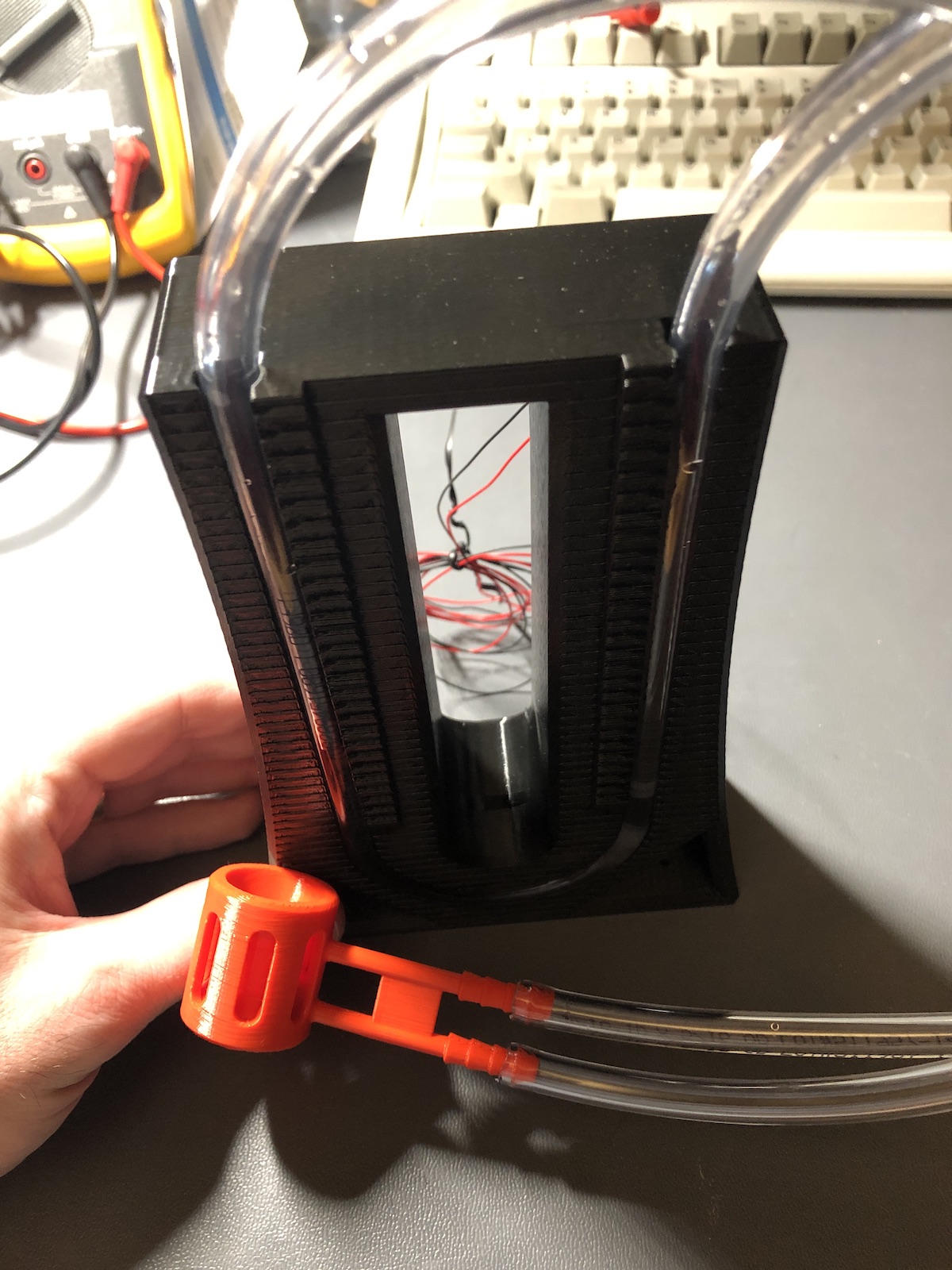
To test the anemometer, I used the "TX RX" example posted by Rob.
The best way to calibrate anemometers would be with a well-characterized wind tunnel. I found ample information online about how to construct a wind tunnerl, from a NASA page covering the basics for K-12 students to a NATO wind tunnel calibration handbook.
Building a wind tunnel is a bit beyond the scope of this week's assignment. While absolute calibration would require a calibrated reference, I can at least calibrate relative to a constant uncalibrated reference. To do this I held the probe at the outlet of my home vacuum cleaner:
Hot-wire anemometer
Hot-wire anemometer
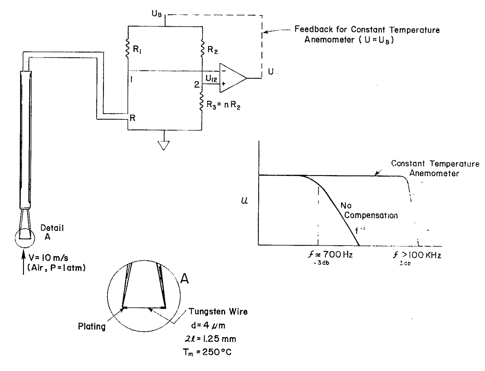
A basic circuit for constant-temperature operation of a "hot-wire" (or in this case thermistor) sensor can be found on page 16 of this thesis:
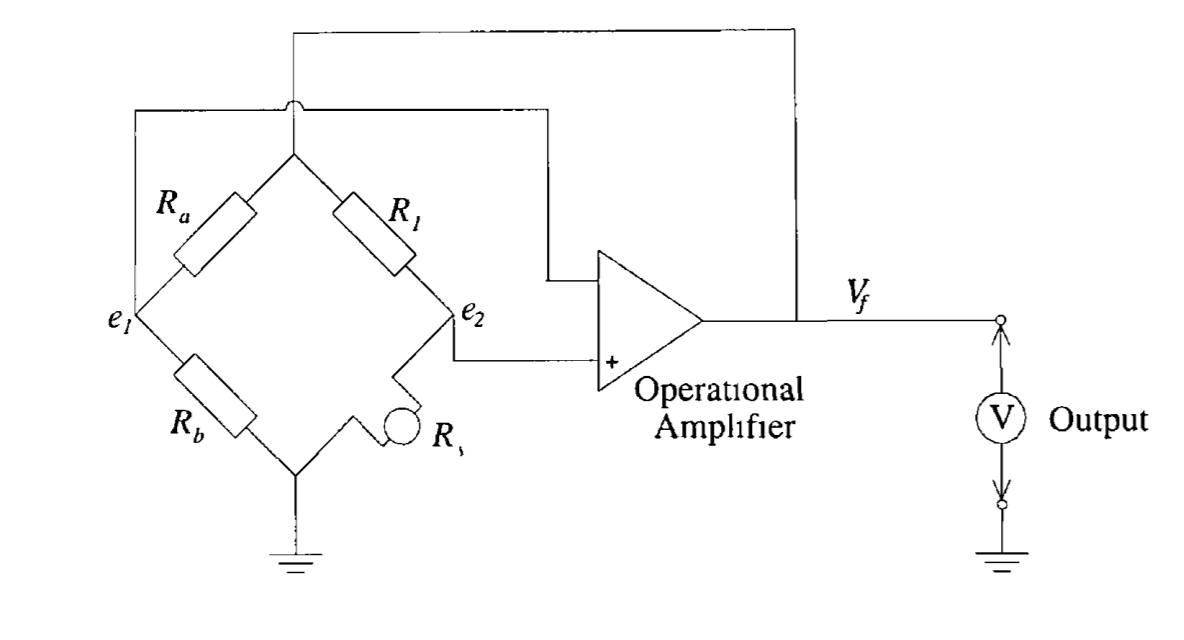
As it turns out, this is essentially the same circuit shown in the paper Rob referenced in his exploration, Thermal anemometry, current state, and future directions from the Review of Scientific Instruments.
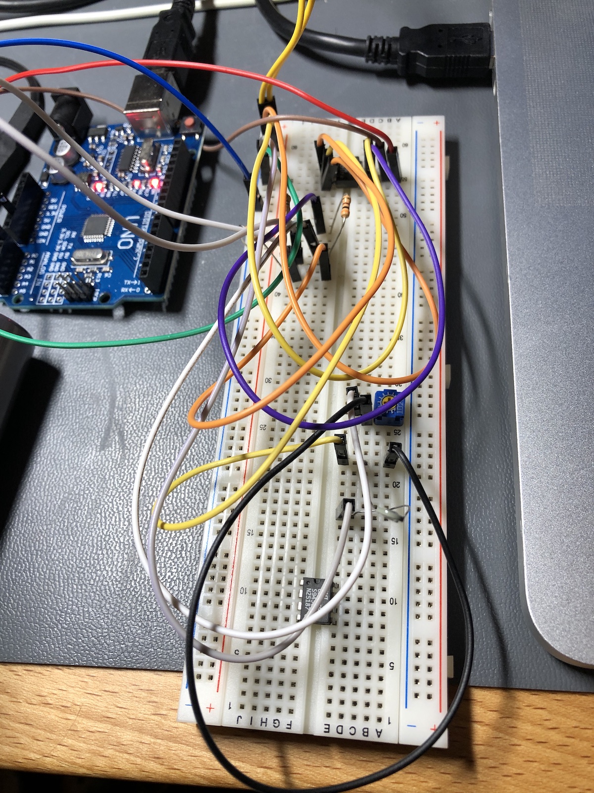
I build a circuit using an OP80GP operational amplifier configured as in the circuit above (with a small trim pot in-line with an NTC thermistor), connected to a 7.5V supply.
Unfortunately, my vacuum cleaner puts out warm air, which would affect the hot-wire anemometer and could not be used for comparison. I was able to show a small signal in response to a small desk fan (just plotting via the simple Arduino AnalogInput example):