Electronics
Stepper motor control using a microcontroller
I've never controlled a stepper motor directly before. Rob gave me a brief introduction in person, with the helpful tip that leads of the same coil can be identified by feeling how the motor feels when manually turned normally vs. when two leads of the same coil are shorted. If two leads belong to the same coil, the motor will be more difficult to turn.
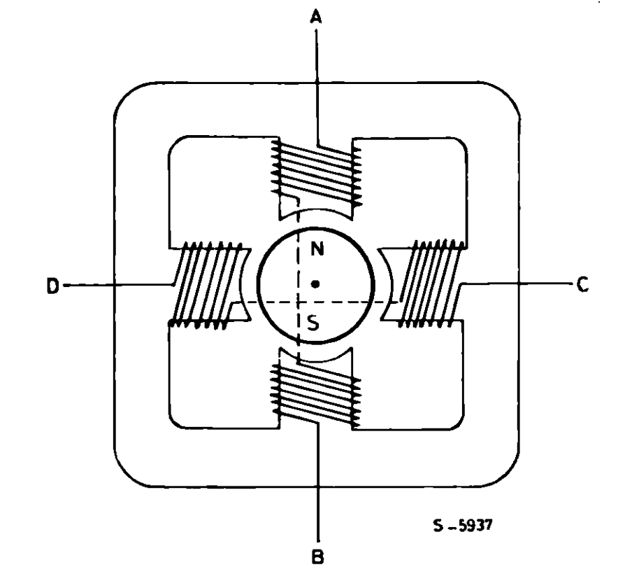
Rob provided me with a bipolar stepper motor, the "Zyltech" 17HD48002H-22B. This is a motor with with four wires coming out, corresponding to the two ends of each of the two coils within. From AN470:
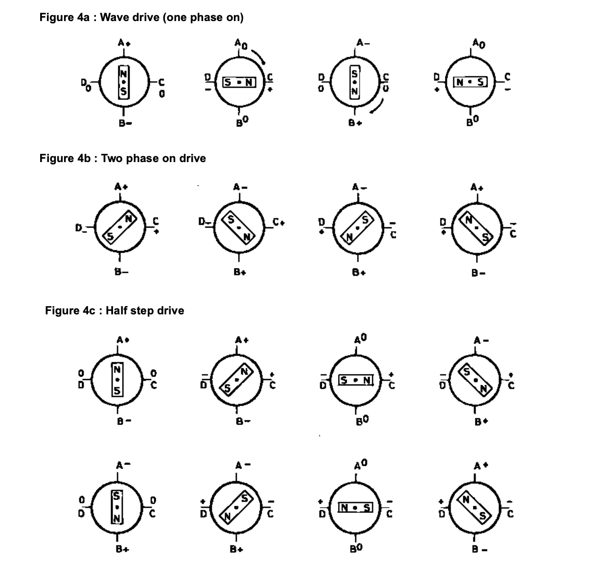
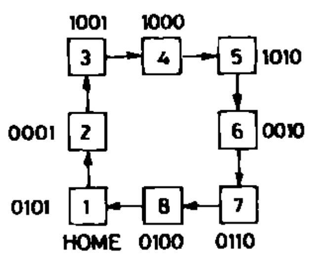
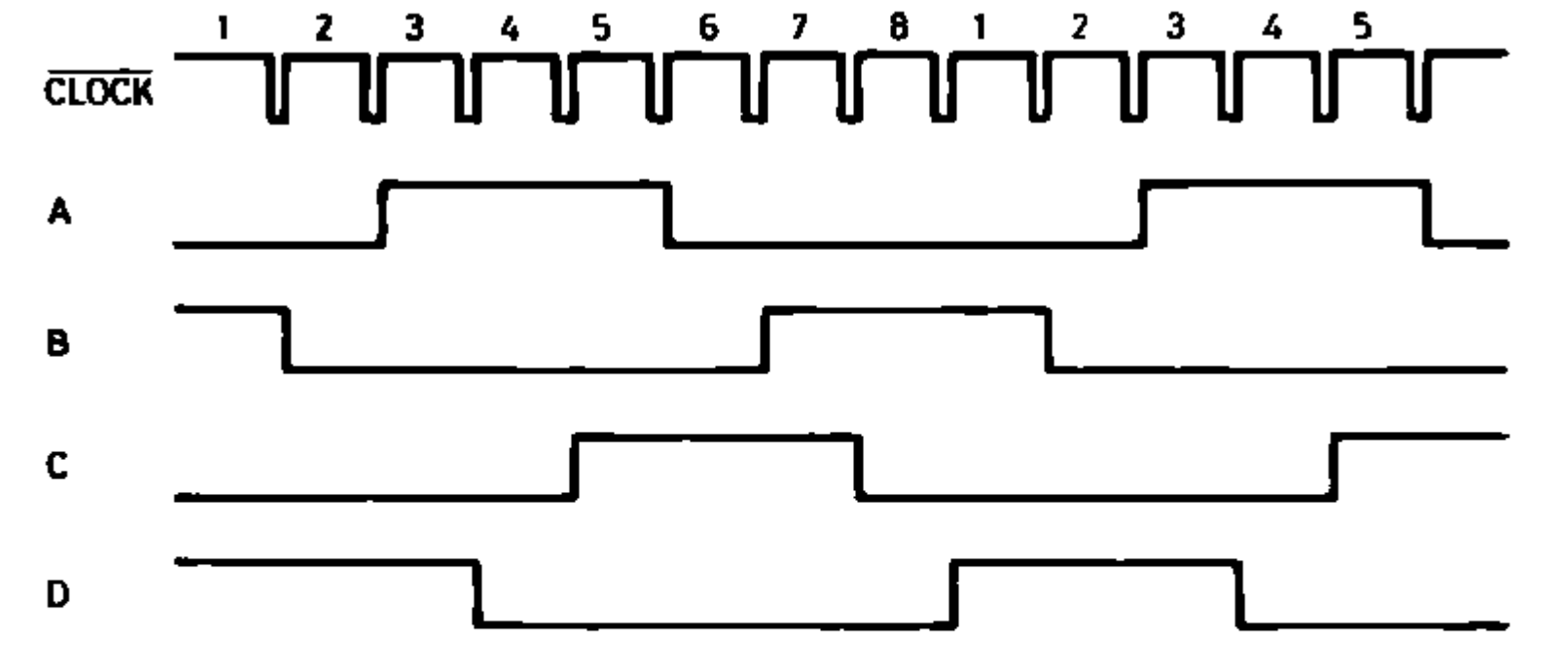
I chose two try half-step drive so the motor would have twice the resolution of the 200 steps it normally supports. Again from AN470, the state diagram for half stepping looks like this:
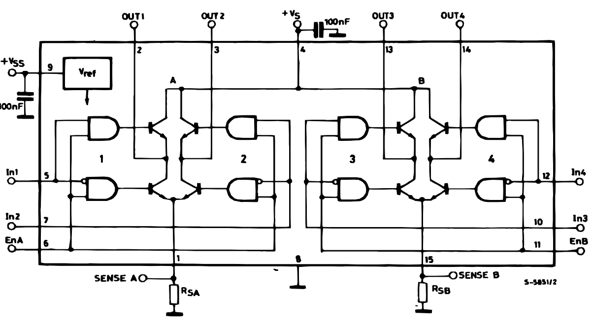
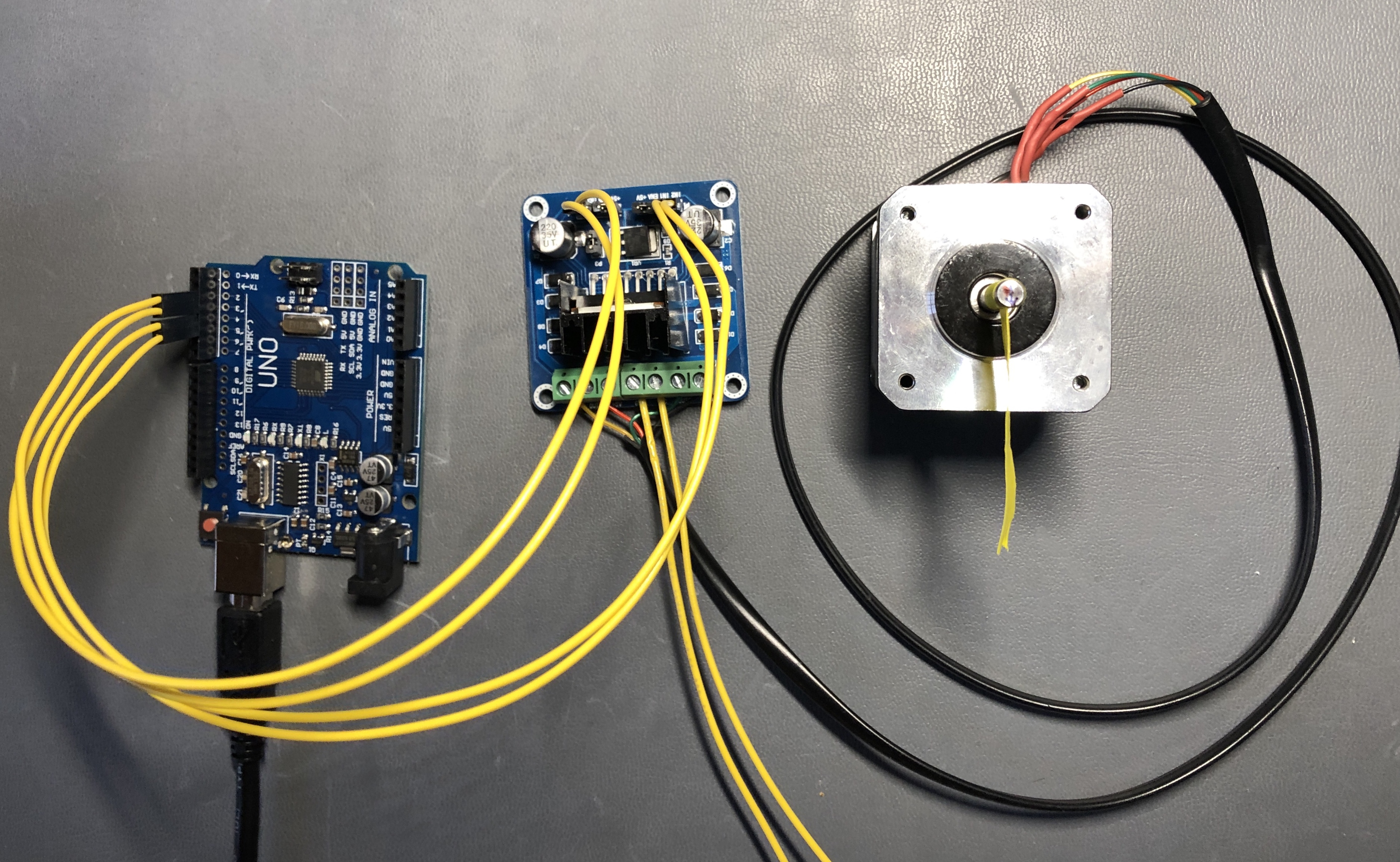
I wired up the stepper control board to an Arduino Uno clone(Arduino D2-5 to IN1-4; shared ground), connected the stepper coils to the control boar (stepper coils to L298 board OUT1-4; L298 board to 4.5VDC supply), wrote some code, and it worked!
Here's the code:
Of course this does not take into account any mechanical forces (i.e. rotational inertia, acceleration, load, etc.), and it's entirely open-loop (i.e. there's no encoder signal coming back from the motor to see if it has actually moved the number of steps expected or if any steps have been lost). Hopefully I'll learn how to include close-loop control in future weeks. The stepper motor is also noisier than I expected (in terms of audio); I'm guessing the square wave driving the motor is to blame. Looking at commercial stepper-control ICs like the "silent" Trinamic TMC2209-LA it seems sinusoidal drive signals are preferred for quiet operation.
In the code above I had to include a small delay after each state change (just a few milliseconds), which I'm assuming is necessary to allow the motor to physically respond to the change in drive signal. I'd like to compare the TTL drive signal with what the L298 actually outputs to see how the two signals compare.
In the demo above, the 17HD48002H-22B stepper is also slower than the stepper motors I've seen operating laser cutters, 3D printers, etc. I'm not sure if that's a function of how I was controlling it, an intrinsic characteristic of this particular motor, or a product of the driver board used. Something to follow up on.